Intel SR2600UR Service Guide - Page 146
Removing Standard Control Panel Module from the Server System
 |
UPC - 735858206778
View all Intel SR2600UR manuals
Add to My Manuals
Save this manual to your list of manuals |
Page 146 highlights
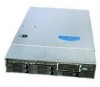
3. Slide the control panel and the cables out through the front of the server system (see letter "B" in Figure 119). Locking Lever A B AF003014 Figure 119. Removing Standard Control Panel Module from the Server System 4. Connect the USB and data cables to the replacement control panel (see letter "A" in Figure 120) 5. Feed the cables of the replacement control panel through the chassis opening (see letter "B" in Figure 120). Data Cable A USB Cable ControlLPoacnael l B AF003015 Figure 120. Connecting the Control Panel Cables 6. Slide the replacement control panel into the server system (see letter "A" in Figure 121) until it clicks into place. 126 Intel® Server System SR2600UR/SR2625UR Service Guide
-
 1
1 -
2
-
3
-
4
-
5
-
6
-
7
-
8
-
9
-
10
-
11
-
12
-
13
-
14
-
15
-
16
-
17
-
18
-
19
-
20
-
21
-
22
-
23
-
24
-
25
-
26
-
27
-
28
-
29
-
30
-
31
-
32
-
33
-
34
-
35
-
36
-
37
-
38
-
39
-
40
-
41
-
42
-
43
-
44
-
45
-
46
-
47
-
48
-
49
-
50
-
51
-
52
-
53
-
54
-
55
-
56
-
57
-
58
-
59
-
60
-
61
-
62
-
63
-
64
-
65
-
66
-
67
-
68
-
69
-
70
-
71
-
72
-
73
-
74
-
75
-
76
-
77
-
78
-
79
-
80
-
81
-
82
-
83
-
84
-
85
-
86
-
87
-
88
-
89
-
90
-
91
-
92
-
93
-
94
-
95
-
96
-
97
-
98
-
99
-
100
-
101
-
102
-
103
-
104
-
105
-
106
-
107
-
108
-
109
-
110
-
111
-
112
-
113
-
114
-
115
-
116
-
117
-
118
-
119
-
120
-
121
-
122
-
123
-
124
-
125
-
126
-
127
-
128
-
129
-
130
-
131
-
132
-
133
-
134
-
135
-
136
-
137
-
138
-
139
-
140
-
 141
141 -
 142
142 -
 143
143 -
 144
144 -
 145
145 -
 146
146 -
 147
147 -
 148
148 -
 149
149 -
 150
150 -
 151
151 -
152
-
153
-
154
-
155
-
156
-
157
-
158
-
159
-
160
-
161
-
162
-
163
-
164
-
165
-
166
-
167
-
168
-
169
-
170
-
171
-
172
-
173
-
174
-
175
-
176
-
177
-
178
-
179
-
180
-
181
-
182
-
183
-
184
-
185
-
186
-
187
-
188
-
189
-
190
-
191
-
192
-
193
-
194
-
195
-
196
-
197
-
198
-
199
-
200
-
201
-
202
-
203
-
204
-
205
-
206
-
207
-
208
-
209
-
210
-
211
-
212
-
213
-
214
-
215
-
216
-
217
-
218
-
219
-
220
-
221
-
222
-
223
-
224
-
225
-
226
-
227
-
228
-
229
-
230
-
231
-
232
-
233
-
234
 |
 |

126
Intel
®
Server System SR2600UR/SR2625UR Service Guide
3.
Slide the control panel and the cables out through the front of the server system (see
letter “B” in
Figure 119
).
Figure 119. Removing Standard Control Panel Module from the Server System
4.
Connect the USB and data cables to the replacement control panel (see letter “A” in
Figure 120
)
5.
Feed the cables of the replacement control panel through the chassis opening (see
letter “B” in
Figure 120
).
Figure 120. Connecting the Control Panel Cables
6.
Slide the replacement control panel into the server system (see letter “A” in
Figure 121
) until it clicks into place.
A
Locking
Lever
B
AF003014
Local
Control Panel
A
B
USB
Cable
Data
Cable
AF003015