Intel SR2600UR Service Guide - Page 45
Power/Sleep Button, Power/Sleep LED - blue screen
 |
UPC - 735858206778
View all Intel SR2600UR manuals
Add to My Manuals
Save this manual to your list of manuals |
Page 45 highlights
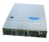
A B C D E F O N ML KJ I H G AF000031 Callout A. B. C. D. E. F. G. H. I. J. K. L. Feature USB Port LCD Display Menu Control Button, Scroll Up Menu Control Button, Scroll Down Menu Control Button, Scroll Left Menu Control Button, Enter System Identification LED Power/Sleep LED Power/Sleep Button System Status LED NIC 2 Activity LED NIC 1 Activity LED Function Allows you to attach a USB component to the front of the system. Screen on which system information is displayed. Scroll up one option at a time. Scroll down one option at a time. Move to the previous option. Select option. Solid blue indicates system identification is active. No light indicates system identification is not activated. Continuous green light indicates the system has power applied to it or the system is is S0 state. Blinking green indicates the system is in sleep or ACPI S1 state. No light indicates the power is off or the system is in ACPI S4 or S5 state. Continuous green light indicates a link between the system and the network to which it is connected. Blinking green light indicates network activity. Solid green indicates normal operation. Blinking green indicates degraded performance. Solid amber indicates a critical or non-recoverable condition. Blinking amber indicates a non-critical condition. No light indicates POST is running or the system is off. Continuous green light indicates a link between the system and the network to which it is connected. Blinking green light indicates network activity. Intel® Server System SR2600UR/SR2625UR Service Guide 25
-
 1
1 -
2
-
3
-
4
-
5
-
6
-
7
-
8
-
9
-
10
-
11
-
12
-
13
-
14
-
15
-
16
-
17
-
18
-
19
-
20
-
21
-
22
-
23
-
24
-
25
-
26
-
27
-
28
-
29
-
30
-
31
-
32
-
33
-
34
-
35
-
36
-
37
-
38
-
39
-
 40
40 -
 41
41 -
 42
42 -
 43
43 -
 44
44 -
 45
45 -
 46
46 -
 47
47 -
 48
48 -
 49
49 -
 50
50 -
51
-
52
-
53
-
54
-
55
-
56
-
57
-
58
-
59
-
60
-
61
-
62
-
63
-
64
-
65
-
66
-
67
-
68
-
69
-
70
-
71
-
72
-
73
-
74
-
75
-
76
-
77
-
78
-
79
-
80
-
81
-
82
-
83
-
84
-
85
-
86
-
87
-
88
-
89
-
90
-
91
-
92
-
93
-
94
-
95
-
96
-
97
-
98
-
99
-
100
-
101
-
102
-
103
-
104
-
105
-
106
-
107
-
108
-
109
-
110
-
111
-
112
-
113
-
114
-
115
-
116
-
117
-
118
-
119
-
120
-
121
-
122
-
123
-
124
-
125
-
126
-
127
-
128
-
129
-
130
-
131
-
132
-
133
-
134
-
135
-
136
-
137
-
138
-
139
-
140
-
141
-
142
-
143
-
144
-
145
-
146
-
147
-
148
-
149
-
150
-
151
-
152
-
153
-
154
-
155
-
156
-
157
-
158
-
159
-
160
-
161
-
162
-
163
-
164
-
165
-
166
-
167
-
168
-
169
-
170
-
171
-
172
-
173
-
174
-
175
-
176
-
177
-
178
-
179
-
180
-
181
-
182
-
183
-
184
-
185
-
186
-
187
-
188
-
189
-
190
-
191
-
192
-
193
-
194
-
195
-
196
-
197
-
198
-
199
-
200
-
201
-
202
-
203
-
204
-
205
-
206
-
207
-
208
-
209
-
210
-
211
-
212
-
213
-
214
-
215
-
216
-
217
-
218
-
219
-
220
-
221
-
222
-
223
-
224
-
225
-
226
-
227
-
228
-
229
-
230
-
231
-
232
-
233
-
234
 |
 |
