Konica Minolta AccurioPrint 2100 GBC Binder G1 User Manual - Page 5
Binder G1 Overview
 |
View all Konica Minolta AccurioPrint 2100 manuals
Add to My Manuals
Save this manual to your list of manuals |
Page 5 highlights
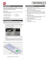
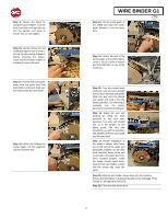
4. BINDER G1 OVERVIEW The picture below shows an overview of the BINDER G1 system. Key User Interface locations are identified. Functional areas are identified to aid the user in troubleshooting. A jam can be categorized by identifying where in the BINDER G1 the jam occurs. WIRE BINDER G1 GB BINDER G1 Overview 1. Area 1 This refers to the area of the BINDER G1 where sheets are fed in and are either bypassed through the BINDER G1, or redirected into the BINDER G1 for binding 2. Area 2 Refers to the area of the BINDER G1 where sheets are transferred onto the twin loop wire for binding. 3. Area 3a Refers to the area of the BINDER G1 where twin loop wire is fed off the supply spool and cut to length for binding. Area 3 primarily refers to wire feed, not paper stacking. 4. Area 3b Refers to the area of the BINDER G1 where the closer and holder are located. The closer compresses the open binding element to finish the book. The Holder holds the element while sheets stack. 5. Area 4 Refers to the area of the BINDER G1 where bound books are stacked. 6. Book Drawer Pulling the Book Drawer handle will allow the user to access the completed book stack for removal. The book drawer is only to be opened when the printer is in standby. 7. Element Feeder Door Open the door and release the Element Feeder tray to access the twin loop supply spool. The element feeder door is only to be opened when the printer is in standby. 8. Upper Transport Release Release the latch and raise the lid to open the upper section of the bypass panel. The lower bypass panel can also be raised, by lifting the handle. Access this area of the machine for jam clearance. 9. LCD Display The LCD will provide key information about the system, and also allow the user to access settings on the BINDER G1. 10. AC Power Supply Location for the power supply cord. Use only the cord provided. 11. Power Switch Use to turn off power to the BINDER G1 during service, or if the BINDER G1 will not be used for a long period of time. 5
-
 1
1 -
 2
2 -
 3
3 -
 4
4 -
 5
5 -
 6
6 -
 7
7 -
 8
8 -
 9
9 -
 10
10 -
 11
11 -
12
-
13
-
14
-
15
-
16
-
17
-
18
-
19
-
20
-
21
-
22
-
23
-
24
-
25
-
26
-
27
-
28
-
29
-
30
-
31
-
32
-
33
-
34
-
35
-
36
-
37
-
38
-
39
-
40
-
41
-
42
-
43
-
44
-
45
-
46
-
47
-
48
-
49
-
50
-
51
-
52
-
53
-
54
-
55
-
56
-
57
-
58
-
59
-
60
-
61
-
62
-
63
-
64
-
65
-
66
-
67
-
68
-
69
-
70
-
71
-
72
-
73
-
74
-
75
-
76
-
77
-
78
-
79
-
80
-
81
-
82
-
83
-
84
-
85
-
86
-
87
-
88
-
89
-
90
-
91
-
92
-
93
-
94
-
95
-
96
-
97
-
98
-
99
-
100
-
101
-
102
-
103
-
104
-
105
-
106
-
107
-
108
-
109
-
110
-
111
-
112
-
113
-
114
-
115
-
116
-
117
-
118
-
119
-
120
-
121
-
122
-
123
-
124
-
125
-
126
-
127
-
128
-
129
-
130
-
131
-
132
-
133
-
134
-
135
-
136
-
137
-
138
-
139
-
140
-
141
-
142
-
143
-
144
-
145
-
146
-
147
-
148
-
149
-
150
-
151
-
152
-
153
-
154
-
155
-
156
-
157
-
158
-
159
-
160
 |
 |
