Konica Minolta AccurioPrint 2100 GBC Binder G1 User Manual - Page 6
Binder G1 Dies, Quick Start Guide, User Operations
 |
View all Konica Minolta AccurioPrint 2100 manuals
Add to My Manuals
Save this manual to your list of manuals |
Page 6 highlights
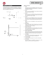
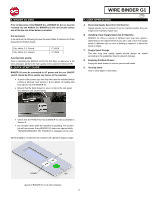
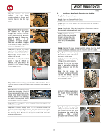
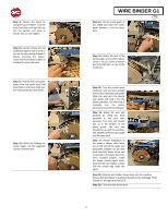
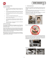
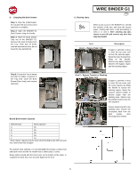
5. BINDER G1 DIES Prior to Operation of the BINDER G1, a BINDER G1 die set must be installed into the PUNCH G2. BINDER G1 will not function unless one of the die sets listed below is installed. Die Set Details A die set from the following list must be used. Refer to Section 10 of this document for further details. Die, eWire, 3:1, Round Die, eWire, 3:1, Square 7714915 7714916 Punched Hole Quality Prior to operating the BINDER G1 for the first time, or whenever a die set is changed, perform the hole quality check outlined in Section 9 B. 6. QUICK START GUIDE BINDER G1 must be connected to AC power and the rear ON/OFF switch should be ON to enable any feature of the machine. A spool of the correct size twin loop wire must be installed before running a bind job. See Section 7 B for details on loading twin loop spools into the BINDER G1 Ensure that the book drawer in area 4 is set to the size paper you intend to use, shown below. WIRE BINDER G1 GB 7. USER OPERATIONS A. Removing Supply Spool from the Machine: Supply spools can be removed from the machine before they are empty to be stored for future use. B. Installing a New Supply Spool into the Machine: BINDER G1 offers a variety of different twin loop wire options, depending on the requirements of your job. Load a new wire supply spool if a different size or color of binding is required, or when the spool is empty. C. Supply Spool Storage: The twin loop wire supply spools should always be stored according to the guidelines listed to prevent damage. D. Emptying the Book Drawer: Empty the book drawer to remove your bound books. E. Clearing Jams: How to clear paper or wire jams. Check that the PUNCH G2 has a BINDER G1 die as detailed in Section 5. Do not open doors while the machine is operating. The current job will not resume if any BINDER G1 doors are opened while "RUNNING BINDING" OR "PAUSED" is displayed on the LCD. When binding is not directed the machine will operate in bypass mode. UP DOWN OK Layout of BINDER G1 LCD User Interface 6
-
 1
1 -
 2
2 -
 3
3 -
 4
4 -
 5
5 -
 6
6 -
 7
7 -
 8
8 -
 9
9 -
 10
10 -
 11
11 -
 12
12 -
13
-
14
-
15
-
16
-
17
-
18
-
19
-
20
-
21
-
22
-
23
-
24
-
25
-
26
-
27
-
28
-
29
-
30
-
31
-
32
-
33
-
34
-
35
-
36
-
37
-
38
-
39
-
40
-
41
-
42
-
43
-
44
-
45
-
46
-
47
-
48
-
49
-
50
-
51
-
52
-
53
-
54
-
55
-
56
-
57
-
58
-
59
-
60
-
61
-
62
-
63
-
64
-
65
-
66
-
67
-
68
-
69
-
70
-
71
-
72
-
73
-
74
-
75
-
76
-
77
-
78
-
79
-
80
-
81
-
82
-
83
-
84
-
85
-
86
-
87
-
88
-
89
-
90
-
91
-
92
-
93
-
94
-
95
-
96
-
97
-
98
-
99
-
100
-
101
-
102
-
103
-
104
-
105
-
106
-
107
-
108
-
109
-
110
-
111
-
112
-
113
-
114
-
115
-
116
-
117
-
118
-
119
-
120
-
121
-
122
-
123
-
124
-
125
-
126
-
127
-
128
-
129
-
130
-
131
-
132
-
133
-
134
-
135
-
136
-
137
-
138
-
139
-
140
-
141
-
142
-
143
-
144
-
145
-
146
-
147
-
148
-
149
-
150
-
151
-
152
-
153
-
154
-
155
-
156
-
157
-
158
-
159
-
160
 |
 |
