McAfee DTP-1650-MGRA Installation Guide - Page 12
Integrate the appliance using a SPAN port, Save the configuration on the switch.
 |
View all McAfee DTP-1650-MGRA manuals
Add to My Manuals
Save this manual to your list of manuals |
Page 12 highlights
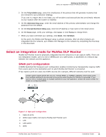
1 Setting up the hardware Select an integration mode for McAfee DLP Monitor This method requires a change on the LAN switch, but no downtime is required because network traffic is not disrupted. With this configuration, some packets might be dropped under heavy loads. As a result, the number of packets seen by McAfee DLP Monitor might not match the number seen by the ports being monitored. Integrate the appliance using a SPAN port Task 1 Connect McAfee DLP Monitor to a network switch using a console cable or network connection (such as Telnet or SSH). Note the port used to connect the appliance to the LAN switch, and the port used by the WAN router. 2 Apply the appropriate SPAN port configuration. 3 Using interface show commands on the switch, verify that traffic is being received on the switch port to which McAfee DLP Monitor is connected. 4 Save the configuration on the switch. Common configuration If a SPAN port is configured on a Cisco switch, the WAN router would be connected to interface "GigabitEthernet1/0/1". The DLP appliance would be connected to interface "GigabitEthernet1/0/2". Switch: configure terminal Switch(config)# interface GigabitEthernet1/0/2 Switch(config‑if)# port monitor GigabitEthernet1/0/1 Switch(config‑if)# end Switch# show port monitor Monitor Port Port being monitored GigabitEthernet1/0/2 GigabitEthernet1/0/1 Switch# write memory 12 McAfee Data Loss Prevention 9.2.1 Installation Guide
-
 1
1 -
2
-
3
-
4
-
5
-
6
-
 7
7 -
 8
8 -
 9
9 -
 10
10 -
 11
11 -
 12
12 -
 13
13 -
 14
14 -
 15
15 -
 16
16 -
 17
17 -
18
-
19
-
20
-
21
-
22
-
23
-
24
-
25
-
26
-
27
-
28
-
29
-
30
-
31
-
32
-
33
-
34
-
35
-
36
-
37
-
38
-
39
-
40
-
41
-
42
-
43
-
44
-
45
-
46
-
47
-
48
-
49
-
50
-
51
-
52
-
53
-
54
-
55
-
56
-
57
-
58
-
59
-
60
-
61
-
62
-
63
-
64
-
65
-
66
-
67
-
68
-
69
-
70
-
71
-
72
-
73
-
74
-
75
-
76
-
77
-
78
 |
 |