McAfee DTP-1650-MGRA Installation Guide - Page 13
Network tap configuration, Network tap types
 |
View all McAfee DTP-1650-MGRA manuals
Add to My Manuals
Save this manual to your list of manuals |
Page 13 highlights
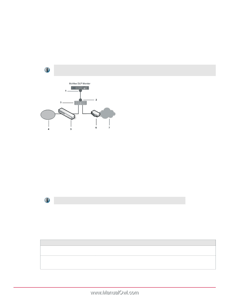
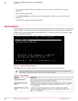
Setting up the hardware Select an integration mode for McAfee DLP Monitor 1 Network tap configuration A network tap configuration enables monitoring by injecting a tap in between two network devices (generally the LAN switch and the WAN router) using additional cabling, then connecting the tap to McAfee DLP Monitor. The network tap captures traffic through a tap that is attached to the LAN switch and WAN router through two network ports. Traffic from these ports flows directly to the capture ports on McAfee DLP Monitor. In environments where there is a firewall or a series of devices separating the LAN switch from the WAN router, the network tap should be installed between the LAN switch and the first device. Figure 1-5 Network tap configuration 1 Capture ports 2 Analyzer ports 3 Network tap 4 LAN 5 LAN switch 6 Router 7 WAN This method requires physical disconnection and reconnection of network cables, so it disrupts traffic. A service window is required. With this configuration, full traffic capture is done even under heavy load conditions. Network tap types Network taps are available in copper or fiber media. Regeneration taps for both types can be used to extend monitoring to multiple ports. When these taps are used, signals are regenerated before sending a copy of the packets to the monitor port. Table 1-1 Network tap types Network tap type Description Copper and copper regenerative These taps use twisted pair copper cabling (preferably CAT6 twisted pair). Fiber and fiber regenerative These taps use multimode fiber cabling with an LC connector on one end (which connects to a capture port on the appliance) and an SC connector on the other (which connects to a port on the tap). McAfee Data Loss Prevention 9.2.1 Installation Guide 13
-
 1
1 -
2
-
3
-
4
-
5
-
6
-
7
-
 8
8 -
 9
9 -
 10
10 -
 11
11 -
 12
12 -
 13
13 -
 14
14 -
 15
15 -
 16
16 -
 17
17 -
 18
18 -
19
-
20
-
21
-
22
-
23
-
24
-
25
-
26
-
27
-
28
-
29
-
30
-
31
-
32
-
33
-
34
-
35
-
36
-
37
-
38
-
39
-
40
-
41
-
42
-
43
-
44
-
45
-
46
-
47
-
48
-
49
-
50
-
51
-
52
-
53
-
54
-
55
-
56
-
57
-
58
-
59
-
60
-
61
-
62
-
63
-
64
-
65
-
66
-
67
-
68
-
69
-
70
-
71
-
72
-
73
-
74
-
75
-
76
-
77
-
78
 |
 |