Netgear DG834G DG834Gv4 Reference Manual - Page 82
Point-to-Point Bridge Configuration, Remote MAC Address
 |
UPC - 606449029918
View all Netgear DG834G manuals
Add to My Manuals
Save this manual to your list of manuals |
Page 82 highlights
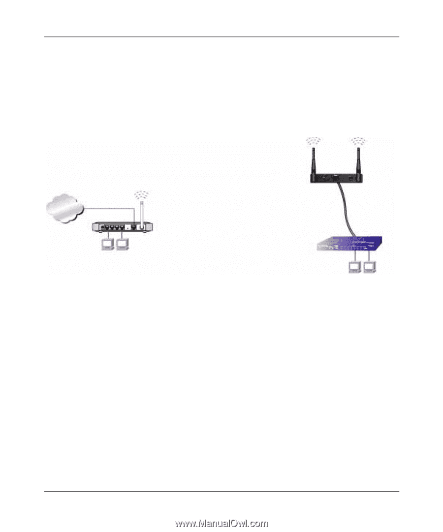
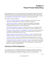
ADSL2+ Modem Wireless Router DG834G Reference Manual Point-to-Point Bridge Configuration In Point-to-Point Bridge mode, the DG834G v4 modem router communicates as an access point with another bridge-mode wireless station. As a bridge, wireless client associations are disabled- only wired clients can be connected. You must enter the MAC address of the other bridge-mode wireless station in the field provided. Use wireless security to protect this communication. The following figure shows an example of Point-to-Point Bridge mode. Both APs (access points) are in AP 2 Point-to-Point Bridge mode. Internet 192.168.0.1 AP 1 (DG834v3 Modem Router) Switch or hub PC's LAN Segment 1 LAN Segment 2 PC's Figure 5-8 To set up a point-to-point bridge configuration (shown in Figure 5-8): 1. Configure the DG834G v4 modem router (AP 1) on LAN Segment 1 in Point-to-Point Bridge mode. 2. Configure the other access point (AP 2) on LAN Segment 2 in Point-to-Point Bridge mode. The DG834G v4 modem router must have AP 2's MAC address in its Remote MAC Address field, and AP 2 must have the DG834G v4's MAC address in its Remote MAC Address field. 3. Configure and verify the following for both access points: • Both APs must use the same SSID, channel, authentication mode, if any, and security settings if security is in use. 4. Disable the DHCP server on AP2. AP1 will then be the DHCP server. 5. Verify connectivity across LAN Segment 1 and LAN Segment 2. A computer on either LAN segment should be able to connect to the Internet or share files and printers of any other PCs or servers connected to LAN Segment 1 or LAN Segment 2. 5-14 v2.0, September 2007 Advanced Configuration
-
 1
1 -
2
-
3
-
4
-
5
-
6
-
7
-
8
-
9
-
10
-
11
-
12
-
13
-
14
-
15
-
16
-
17
-
18
-
19
-
20
-
21
-
22
-
23
-
24
-
25
-
26
-
27
-
28
-
29
-
30
-
31
-
32
-
33
-
34
-
35
-
36
-
37
-
38
-
39
-
40
-
41
-
42
-
43
-
44
-
45
-
46
-
47
-
48
-
49
-
50
-
51
-
52
-
53
-
54
-
55
-
56
-
57
-
58
-
59
-
60
-
61
-
62
-
63
-
64
-
65
-
66
-
67
-
68
-
69
-
70
-
71
-
72
-
73
-
74
-
75
-
76
-
 77
77 -
 78
78 -
 79
79 -
 80
80 -
 81
81 -
 82
82 -
 83
83 -
 84
84 -
 85
85 -
 86
86 -
 87
87 -
88
-
89
-
90
-
91
-
92
-
93
-
94
-
95
-
96
-
97
-
98
-
99
-
100
-
101
-
102
-
103
-
104
-
105
-
106
-
107
-
108
-
109
-
110
-
111
-
112
-
113
-
114
-
115
-
116
-
117
-
118
-
119
-
120
-
121
-
122
-
123
-
124
-
125
-
126
-
127
-
128
-
129
-
130
-
131
-
132
-
133
-
134
-
135
-
136
-
137
-
138
-
139
-
140
-
141
-
142
-
143
-
144
-
145
-
146
-
147
-
148
-
149
-
150
-
151
-
152
-
153
-
154
-
155
-
156
-
157
-
158
-
159
-
160
-
161
-
162
-
163
-
164
-
165
-
166
-
167
-
168
 |
 |