Sanyo 26KHS72R Installation Instructions
Sanyo 26KHS72R - 25,200 BTU Ductless Single Zone Mini-Split Wall-Mounted Heat Pump Manual
 |
View all Sanyo 26KHS72R manuals
Add to My Manuals
Save this manual to your list of manuals |
Sanyo 26KHS72R manual content summary:
- Sanyo 26KHS72R | Installation Instructions - Page 1
INSTRUCTIONS - Split System Heat Pump Air Conditioner - Model Combinations Combine indoor and outdoor units only as listed below. Indoor Units and Outdoor Units Indoor Unit Type 26 X 4-Way Air Remote Controller comes with Owner's Manual and Installation Instructions. SC System Controller SHA- - Sanyo 26KHS72R | Installation Instructions - Page 2
help for a special problem, contact our sales/service outlet or your certified dealer for additional instructions. In Case of Improper to reduce strain on your back. Sharp edges or thin aluminum fins on the air conditioner can cut your fingers. When Installing... ...In a Room Properly insulate any - Sanyo 26KHS72R | Installation Instructions - Page 3
by curtailing heat and carrying power, etc. Most importantly, the multi air conditioner system is able to replenish a large amount of refrigerant compared to conventional individual air conditioners. If a single unit of the multi air conditioner system is to be installed in a small room, select - Sanyo 26KHS72R | Installation Instructions - Page 4
for R410A. Flaring oil Yes No For systems that use R22, apply mineral oil (Suniso oil) to the flare nuts on the tubing to prevent refrigerant leakage. For machines that use R407C or R410A, apply synthetic oil (ether oil) to the flare nuts. Manifold gauge Vacuum pump Outlet Inlet * Using tools - Sanyo 26KHS72R | Installation Instructions - Page 5
the minimum necessary amount to the charging cylinder before using it to charge the air conditioning unit. Configuration and characteristics of cylinders Valve Liquid Single valve Charge liquid refrigerant with cylinder in up-side-down position. Fig. 1 Valve Liquid Single valve (with siphon - Sanyo 26KHS72R | Installation Instructions - Page 6
for Installation Using New Refrigerant 1. GENERAL 8 Removing the Ceiling Panel for Servicing 3-9. Duct for Fresh Air I Wall-Mounted Type Side Tubing 3-15. Wiring Instructions 3-16. Wiring Instructions for Inter-Unit Connections 3-17 Indoor Temperature Sensor 6-7. Trouble Diagnostics 7. HOW TO - Sanyo 26KHS72R | Installation Instructions - Page 7
8-7. Memory Back Up Switch 8-8. Test Run 9. HOW TO PROCESS TUBING 97 9-1. Connecting the Refrigerant Tubing 9-2. Connecting Tubing between Indoor and Outdoor Units 9-3. Insulating the Refrigerant Tubing 9-4. Taping the Tubes 9-5. Finishing the Installation 10. LEAK TEST, EVACUATION AND ADDITIONAL - Sanyo 26KHS72R | Installation Instructions - Page 8
briefly outlines where and how to install the air conditioning system. Please read over the entire set of instructions for the indoor and outdoor units and make , check any specified instructions or limitations. 1-4. Additional Materials Required for Installation 1. Refrigeration (armored) tape 2. - Sanyo 26KHS72R | Installation Instructions - Page 9
XH / XHW (4-Way Air Discharge Semi-Concealed) Part type Wood screws 2 For XHW type Wire joints Owner's Manual Installation Instructions 2 For XHW type 1 For XHW type 1 For XHW determining location where indoor unit is installed 1 For supporting indoor unit Rawl plug *2 10 For attaching wall - Sanyo 26KHS72R | Installation Instructions - Page 10
For air intake refrigerant tubing 1 For sizing up of liquid tube from 1/4 in. to 3/8 in. (only for 26 type) Wired remote controller (comes with 7-7/8 in. wire) 1 For UHW type Wood screws 2 For UHW type Wire joints 2 For UHW type Owner's Manual 1 For UHW type Installation Instructions - Sanyo 26KHS72R | Installation Instructions - Page 11
07-115 SSHP_II 5/7/07 3:59 PM Page 11 Table 1-5 (Accessories for the Wired Remote Controller) Part Name Figure 'Q'ty Part Name Wired remote controller (comes with 7-7/8 in. wire) 1 Spacers Machine screws M4 × 1 in. 2 Wire joints Wood screws 2 Figure 'Q'ty 2 4 Table 1-6 (Accessories for - Sanyo 26KHS72R | Installation Instructions - Page 12
07-115 SSHP_II 5/7/07 3:59 PM Page 12 Part Name Separate type signal receiving unit (comes with 7-7/8 in. wire) Carrier for ceiling installation Figure 'Q'ty Part Name Small screws 1 M4 × 1-9/16 in. 1 Wood screws Figure 'Q'ty 2 2 Wireless remote controller Wireless remote - Sanyo 26KHS72R | Installation Instructions - Page 13
tubing between the indoor and outdoor units should be kept as short as possible. G The length of the refrigerant tubes between the indoor and outdoor units are limited by the elevation difference between the 2 units. During tubing work, try to make both the tubing - Sanyo 26KHS72R | Installation Instructions - Page 14
43 4.2 10 - 100 b) 0.43 6.2 No additional charge of compressor oil is necessary. *1 If total tubing length becomes 100 to 165 ft., charge additional refrigerant by 0.43 oz./ft. C(H)4272R 3/8 (9.52) 5/8 (15.88) 165 100 50 10 - 100 b) 0.43 7.9 Table 1-11 List of Connection Tube Sizes Main tubing - Sanyo 26KHS72R | Installation Instructions - Page 15
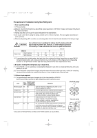
gas density for the room in which the unit is installed. I Check of limit density When installing an air conditioner in a room, it is necessary to ensure that even if the refrigerant gas accidentally escapes, its density does not exceed the limit level. If the density might exceed the limit level - Sanyo 26KHS72R | Installation Instructions - Page 16
be uniformly cooled. G select a location where the ceiling is strong enough to support the weight of the unit. G select a location where tubing and drain pipe not in direct sunlight nor in the flow of cool air from the indoor unit. NOTE Air delivery will be degraded if the distance from the floor to - Sanyo 26KHS72R | Installation Instructions - Page 17
*1 Fig. 2-2 More than 25/64" *4 Hot air Outdoor unit Exhaust fan Heat source Fig. 2-1 Air direction chamber (field supply) (Obstruction above unit) B to reduce humidity and protect the unit against possible water damage and decreased service life. (Fig. 2-4) G use lug bolts or equal to bolt - Sanyo 26KHS72R | Installation Instructions - Page 18
snow and wind In regions with snow and strong wind, the following problems may occur when the outdoor unit is not provided with a platform and be used for the platform, and the platform should be installed beneath the air intake side of outdoor unit. (3) The platform foundation must be firm and - Sanyo 26KHS72R | Installation Instructions - Page 19
9-27/32 21-13/16 1-1/16 15/16 17/32 Unit: inch Note: In snowy regions, if there is concern that snow may enter the air discharge chamber, remove the base of the chamber (10 screws) before using. STK-DRE140A for 4272R unit 11-13/16 1 Unit front - Sanyo 26KHS72R | Installation Instructions - Page 20
07-115 SSHP_II 5/7/07 3:59 PM Page 20 Dimensions of Outdoor Unit with air-discharge chamber (field supply) 2672R / 3072R / 3672R unit with STK-DRV80U 6-11/16 25-31/32 4-5/16 1/2 Wind direction 1/2 25/32 13/32 14-31/ - Sanyo 26KHS72R | Installation Instructions - Page 21
discharge chamber (field supply) C(H)2672R / 3072R / 3672R / 4272R with STK-DRV80U & DRE140A Required space around outdoor unit If the air discharge chamber is used, the space shown below must be secured around the outdoor unit. If the unit is used without the required space, a protective - Sanyo 26KHS72R | Installation Instructions - Page 22
13-25/32 9-3/8 9-3/16 16-25/32 27-29/32 07-115 SSHP_II 5/7/07 3:59 PM Page 22 2-7. Dimensions of Snow Ducting Reference diagram for snow-proof vents (field supply) STK-BDRE80A for 2672R / 3072R / 3672R unit 1 Unit top, snow-proof vent 2 Unit left side 3 Unit right side 4 Unit reverse side 5 - Sanyo 26KHS72R | Installation Instructions - Page 23
07-115 SSHP_II 5/7/07 3:59 PM Page 23 Dimensions of outdoor unit with snow-proof vents (field supply) 2672R / 3072R / 3672R unit with STK-BDRE80A 30-3/32 7-1/16 Wind direction Wind direction 25/32 13/32 25-13/32 14-31/32 15-15/16 Wind direction Wind direction 37 3/4 19/32 11-29/32 - Sanyo 26KHS72R | Installation Instructions - Page 24
07-115 SSHP_II 5/7/07 3:59 PM Page 24 Reference diagram for snow-proof vents - 1 Space requirements for setting - (1) C(H)2672R / 3072R / 3672R / 4272R with STK-BDRE80A & STK-BDR140U [Obstacle to the rear of unit] Top is open: (1) Single-unit installation (2) Obstacles on both sides [Obstacle to - Sanyo 26KHS72R | Installation Instructions - Page 25
07-115 SSHP_II 5/7/07 3:59 PM Page 25 Reference diagram for snow-proof vents - 2 Space requirements for setting - (2) C(H)2672R / 3072R / 3672R / 4272R with STK-BDRE80A & STK-BDR140U [Obstacles to the front and rear of unit] The top and both sides must remain open. Either the obstacle to the front - Sanyo 26KHS72R | Installation Instructions - Page 26
THE INDOOR UNIT I 4-Way Air Discharge Semi-Concealed Type (X Type and 3-2), by attaching them to the ceiling support structure, or by any other method that Refrigerant tubing side Unit: inch Refrigerant tubing joint (gas tube side) Suspension lug Drain connection (other side) (VP25) Refrigerant - Sanyo 26KHS72R | Installation Instructions - Page 27
07-115 SSHP_II 5/7/07 3:59 PM Page 27 3-3. Placing the Unit Inside the Ceiling (1) When placing the unit inside the ceiling, determine the pitch of the suspension bolts using the supplied full-scale installation diagram. (Fig. 3-4) The size of the opening for the indoor unit can be confirmed by - Sanyo 26KHS72R | Installation Instructions - Page 28
or more) and that there are no water traps. CAUTION G Do not install an air bleeder tube, as this may cause water to spray from the drain tube outlet. (Fig connection to the unit. Fasten the pipe to a wall, frame, or other support as close to the unit as possible. (Fig. 3-11) G Provide insulation - Sanyo 26KHS72R | Installation Instructions - Page 29
07-115 SSHP_II 5/7/07 3:59 PM Page 29 3-5. Checking the Drainage After wiring and piping are completed, use the following procedure to check that the water will drain smoothly. For this, prepare a bucket and wiping cloth to catch and wipe up spilled water. WARNING Do not supply power to the unit - Sanyo 26KHS72R | Installation Instructions - Page 30
or you may damage X the unit. Instead, use the remote control unit if you want to change the direction or air flow. 3-6. Before Installing the Ceiling Panel (1) Remove the air-intake grille and air filter from the ceiling panel. (Figs. 3-13 and 3-14) (a) Remove the 2 screws on the latch of the - Sanyo 26KHS72R | Installation Instructions - Page 31
3-6 in reverse. NOTE Rehook the safety cord before closing the air-intake grille. 3-8. When Removing the Ceiling Panel for Servicing When removing the ceiling panel for servicing, remove the air-intake grille and air filter, disconnect the wiring connector inside the electrical component box, and - Sanyo 26KHS72R | Installation Instructions - Page 32
duct connection box with the accessory screws. (M4 × L1/2 in., 4 pcs) (Fig. 3-18) G Put the duct connection box into the rectangular hole of the air-intake plenum and fasten it to both sides of the indoor unit and plenum with the accessory screws. (M4 × L1/2 in., 3 pcs) (Fig. 3-18) (c) Installing - Sanyo 26KHS72R | Installation Instructions - Page 33
to the chamber. Drawing the panel downwards sets the panel in position temporarily with the panel catch (at 2 locations). G Remove the socket cover of the air-intake plenum and pass the 8P sockets through it. (Fix the panel lead wire with the chamber side clamp.) (Fig. 3-17) G Connect the 8P socket - Sanyo 26KHS72R | Installation Instructions - Page 34
07-115 SSHP_II 5/7/07 3:59 PM Page 34 I Wall-Mounted Type (K Type) 3-10. Removing the Wall Fixture from the Unit KH(S)2672R Remove and discard the set screws and take off the rear panel. (Fig. 3-19) NOTE K Tubing can be extended in 3 directions as shown in Fig. 3-20. Select the direction that - Sanyo 26KHS72R | Installation Instructions - Page 35
07-115 SSHP_II 5/7/07 3:59 PM Page 35 KH(S)3072R, KH(S)3672R One hole is required for the air conditioner tubing, and may be either on the left or right side. (Also see section 3-14. Preparing the Indoor Side Tubing.) (1) Tape the full-scale installation - Sanyo 26KHS72R | Installation Instructions - Page 36
07-115 SSHP_II 5/7/07 3:59 PM Page 36 KHH(S)2672R Remove and discard the set screws and take off the wall fixture. (Fig. 3-29) KHH(S)2672R (1) Tape the full-scale installation diagram on the wall at the location selected. Make sure the unit is hori- K zontal using a level or tape measure to - Sanyo 26KHS72R | Installation Instructions - Page 37
. holes in the wall. Insert rawl plugs for appropriate mounting screws. (Fig. 3-36) KH(S)3072R, KH(S)3672R Confirm that the wall is strong enough to support the unit. a) If Wooden Wall (1) Attach the wall fixture to the wall with the 12 screws pro- vided. (Fig. 3-37) If you are not able - Sanyo 26KHS72R | Installation Instructions - Page 38
07-115 SSHP_II 5/7/07 3:59 PM Page 38 KHH(S)2672R Confirm that the wall is strong enough to support the unit. a) If Wooden Wall (1) Attach the wall fixture to the wall with the 9 screws provided. (Fig. 3-38) If you are not able to line - Sanyo 26KHS72R | Installation Instructions - Page 39
remove the grille (1) Set the 2 flaps in the horizontal position. (2) Unscrew the 3 screws. (Fig. 3-40a) (3) Remove the grille. (a) Hold both corners of the air intake grille, then pull out and up to open. (Fig. 3-40b) (b) Use a standard screwdriver to push up the 3 tabs to remove the grille. (Fig - Sanyo 26KHS72R | Installation Instructions - Page 40
07-115 SSHP_II 5/7/07 4:00 PM Page 40 KH(S)3072R, KH(S)3672R How to Remove the Grille (1) Remove the plastic cover. (Fig. 3-42) (2) Remove the clamp for the wiring connector. (Fig. 3-43) (3) Disconnect the 2 wiring connectors. (Fig. 3-44) K (4) Set the flap in the horizontal position. (Fig. 3-45) - Sanyo 26KHS72R | Installation Instructions - Page 41
07-115 SSHP_II 5/7/07 4:00 PM Page 41 3-14. Preparing the Indoor Side Tubing KH(S)2672R Arrangement of tubing by directions (a) Right tubing The corner of the right frame needs to be cut by a hacksaw or the like. (Fig. 3-46) (b) Right-rear or left-rear tubing In this case, the corner of the frame - Sanyo 26KHS72R | Installation Instructions - Page 42
rear tubing (Recommended) Right tubing Right tubing outlet 3-15. Wiring Instructions General Precautions on Wiring (1) Before wiring, confirm the rated voltage wiring must be connected tightly. (5) Do not allow wiring to touch refrigerant tubing, compressor, or any moving parts of the fan. Fig. - Sanyo 26KHS72R | Installation Instructions - Page 43
07-115 SSHP_II 5/7/07 4:00 PM Page 43 3-16. Wiring Instructions for Inter-Unit Connections KH(S)2672R Rear Wall panel (1) Insert the inter-unit wiring (according to local electrical codes) into the through-the-wall PVC - Sanyo 26KHS72R | Installation Instructions - Page 44
and carry out the correct field wiring. Wrong wiring can cause the unit to malfunction. G Check local electrical codes and any specified wiring instructions or limitations. (5) Secure the metallic cover with its screw. Then replace the side cover. KHH(S)2672R KHH(S)2672R Rear panel Wiring Wall - Sanyo 26KHS72R | Installation Instructions - Page 45
then tape as far as the fittings. CAUTION The air conditioner's performance will deteriorate if a tube is crushed. To prevent crushing of tubing, avoid sharp bends. Use a pipe bending tool to bend tubes. (Fig. 3-63) (4) Connect the refrigerant tubing to the outdoor unit. (After performing a leak - Sanyo 26KHS72R | Installation Instructions - Page 46
of the fittings. The drain hose should come straight down the wall to a point where water runoff will not stain the wall. (4) Connect the refrigerant tubing to the outdoor unit.(After performing a leak test on the connection, insulate it with insulating tape. (Fig. 3-70)) Also, refer to Section 10 - Sanyo 26KHS72R | Installation Instructions - Page 47
bolt (M10 or 3/8") (field supply) Fig. 3-75 or (b) Use existing ceiling supports or construct a suitable support as shown in Fig. 3-76. Ceiling tiles Ceiling support WARNING It is important that you use extreme care in supporting the indoor unit from the ceiling. Ensure that the ceiling is - Sanyo 26KHS72R | Installation Instructions - Page 48
07-115 SSHP_II 5/7/07 4:00 PM Page 48 (5) Before suspending the indoor unit, remove the 2 screws on the latch of the air-intake grilles, open the grilles, and remove them by pushing the claws of the hinges as shown in Fig. 3-78. Then remove both side panels - Sanyo 26KHS72R | Installation Instructions - Page 49
07-115 SSHP_II 5/7/07 4:00 PM Page 49 (7) Suspend the indoor unit as follows. (a) Mount a washer and two hexagonal nuts on each suspension bolt as shown in Fig. 3-82. (b) Lift the indoor unit, and place it on the washers through the notches, to fix it in place. (Fig. 3-83) (c) Tighten the two - Sanyo 26KHS72R | Installation Instructions - Page 50
panel top of the indoor unit for drawing in fresh air. If it is necessary to draw in fresh air, remove the cover by knocking it out and connect the codes and regulations before obtaining wire. Also, check any specified instruction or limitations. Not good Fig. 3-89 Drain pipe clamp (supplied - Sanyo 26KHS72R | Installation Instructions - Page 51
Service G This air conditioner is usually installed above the ceiling so that the indoor unit and ducts are not visible. Only the air intake and air dimension) 3-15/16 3-17/32 1-7/32 B Refrigerant tubing joint (liquid tube) 13/32 Refrigerant tubing joint (gas tube) Upper drain port (O.D. - Sanyo 26KHS72R | Installation Instructions - Page 52
off the suspension lugs. Hole-in-anchor Hole-in-plug Concrete Insert Suspension bolt (M10 or 3/8") (field supply) Fig. 3-93 Ceiling tiles Ceiling support Fig. 3-94 Nuts and washers (2 sets) Suspension bolt Suspension lug Upper Lower Fig. 3-95 Suspension bolt Hexagonal nut Fig. 3-96 52 - Sanyo 26KHS72R | Installation Instructions - Page 53
07-115 SSHP_II 5/7/07 4:00 PM Page 53 G Fig. 3-97 shows an example of installation. Air outlet duct Air-outlet grille Ceiling material Indoor unit Bolt anchor Suspension bolt Air-intake duct Air-intake grille U Fig. 3-97 3-24. Installing the Drain Piping (1) Prepare standard hard PVC pipe for - Sanyo 26KHS72R | Installation Instructions - Page 54
its connection to the unit. Fasten the pipe to a wall, frame, or other support as close to the unit as possible. (Fig. 3-103) 3-25. Checking the use long screws as they may puncture the drain pan and cause water leak-age. 54 Air bleeder Not good Fig. 3-100 Good 11-13/16 in. or less 19-11/16 - Sanyo 26KHS72R | Installation Instructions - Page 55
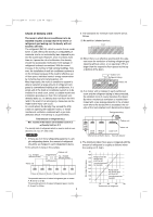
49 Pa at "H" position. If external static pressure is too great (due to long extension of duct, for example), the air flow volume may drop too low at each air outlet. This problem may be solved by increasing the fan speed as explained above. External Static Pressure Indoor Fan Performance 26 Type - Sanyo 26KHS72R | Installation Instructions - Page 56
, refer to the instruction manual of the drain socket (optional part STK-DS25T). 4-3. Routing the Tubing and Wiring G The tubing and wiring can be extended out in 4 directions: front, rear, right, and down. Drain port Fig. 4-1 Anchor bolt (M10) Unit: inch G The service - Sanyo 26KHS72R | Installation Instructions - Page 57
to misoperate or become damaged. (5) Do not allow wiring to touch the refrigerant tubing, compressor, or any moving parts of the fan. (6) Unauthorized relevant rules and regulations. (8) To prevent malfunction of the air conditioner caused by electrical noise, care must be taken when wiring as - Sanyo 26KHS72R | Installation Instructions - Page 58
07-115 SSHP_II 5/7/07 4:00 PM Page 58 Indoor Unit Type (B) Power Supply AWG #14 Trade Size of Conduit MOP (Fuse or HACR type circuit breaker) X, K, T, U Max. length 67 ft. 3/4 in. 15 A Control Wiring (C) Inter-Unit Control Wiring AWG #18 Use high voltage wire (300 V)*1 Max. 3,300 ft. (D) - Sanyo 26KHS72R | Installation Instructions - Page 59
hazard may also exist. Therefore, ensure that all wiring is tightly connected. When connecting each power wire to the corresponding terminal, follow the instructions on "How to connect wiring to the terminal" and fasten the wire securely with the fixing screw of the terminal plate. 5-4. How to - Sanyo 26KHS72R | Installation Instructions - Page 60
controller in a place where it will be exposed to direct sunlight or near a window or other place where it will be exposed to the outside air. G Be sure to install the remote controller vertically, such as on a wall. G The mounting position for the remote controller should be located in an - Sanyo 26KHS72R | Installation Instructions - Page 61
07-115 SSHP_II 5/7/07 4:00 PM Page 61 6-2. Wired Remote Controller Installation G Do not supply power to the unit or try WARNING to operate it until the tubing and wiring to the outdoor unit are completed. CAUTION G Do not twist the control wiring with the power wiring or run it in the same - Sanyo 26KHS72R | Installation Instructions - Page 62
07-115 SSHP_II 5/7/07 4:00 PM Page 62 6-3. Basic Wiring Diagram 3/32 4-23/32 CAUTION Carry out wiring correctly (incorrect wiring will damage the equipment). Use shielded wires for inter-unit control wiring and ground the shield on both sides. (Fig. 6-5) Otherwise misoperation because of noise - Sanyo 26KHS72R | Installation Instructions - Page 63
07-115 SSHP_II 5/7/07 4:00 PM Page 63 6-4. Wiring System Diagram for Group Control This diagram shows when several units (maximum of 8) are controlled by a remote controller (main unit). In this case, a remote controller can be connected at any indoor unit. I Wiring procedure Wire according to the - Sanyo 26KHS72R | Installation Instructions - Page 64
07-115 SSHP_II 5/7/07 4:00 PM Page 64 6-5. Wiring System Diagram for Multiple Remote Controllers I When Installing Multiple Remote Controllers This multiple remote controller system is used for operating the unit(s) at different positions. (A maximum of 2 remote controllers can be installed.) G - Sanyo 26KHS72R | Installation Instructions - Page 65
in the signal from another indoor unit Error in receiving serial communications signal E18 Communications trouble Communications failure with MDC E31 between units Mis-setting Setting error Indoor unit group settings error L01 Indoor/outdoor unit type mismatch L02 Main unit - Sanyo 26KHS72R | Installation Instructions - Page 66
thermostat P01 protective Float switch P10 device Discharge temperature trouble P03 Outdoor protection High pressure switch or compressor temperature (C1) F06 Outdoor heat exchanger temperature (C2) F07 Outdoor air temperature (TO) F08 Intake temperature (TS) F12 Indoor EEPROM error - Sanyo 26KHS72R | Installation Instructions - Page 67
= 2: P alarm 3: H alarm 4: E alarm 5: F alarm 6: L alarm N = Alarm No. * Refer to "1. Examples of alarm display" below. Insufficient gas indicator Refrigerant recovery mode Automatic address setting Automatic address setting in progress Blinking alternately Automatic address setting alarm (E15 - Sanyo 26KHS72R | Installation Instructions - Page 68
following places: In direct sunlight. Behind a curtain or other place where it is covered. More than 26 ft. away from the air conditioner. In the path of the air conditioner's airstream. Where it may become extremely hot or cold. Where it may be subject to electrical or magnetic interference. (1) If - Sanyo 26KHS72R | Installation Instructions - Page 69
controller depending on the type of indoor unit in which the wireless receiving unit is used. 2 Operation mode switch In this Split System Air Conditioner set the switch to "A". * The switch is factory set to "S" / "A". * Always press the reset button after switching the setting. RC (WL) SKN AHC - Sanyo 26KHS72R | Installation Instructions - Page 70
Discharge Semi-concealed Type (X Type) 7-5. Indicator Section Installation X Remove the ceiling panel and indicator cover and install the indicator section. Air intake grille Mark section (indicator section) (1) Remove the ceiling panel. (2) Remove the corner cover behind the mark sec- tion - Sanyo 26KHS72R | Installation Instructions - Page 71
Mounted Type (T Type) 7-7. Indicator Section Installation Remove the side panel to install the indicator section. (Fig. 7-8) (1) Remove the side panel. Open the air intake grille, remove the screw at one place and then remove the side panel by Indicator section Indicator section Cover B (Not used - Sanyo 26KHS72R | Installation Instructions - Page 72
receiver unit PCB from OFF to the ON position. (2) Press the ON/OFF operation button on the wireless remote controller. (3) Make a test run using the air conditioner in COOL or HEAT mode. (4) During the test run, each of the 3 indicator lamps on the indoor unit flash. (5) During the test run, the - Sanyo 26KHS72R | Installation Instructions - Page 73
indicator lamps on the indoor unit indicate the error cause if the air conditioner fails to operate upon being switched on. The possible alarm indications are (TIMER lamp) (STANDBY lamp) * S.C.: Serial communications Cause of Trouble S.C. errors* between the indoor unit's controller (PCB) and the - Sanyo 26KHS72R | Installation Instructions - Page 74
07-115 SSHP_II 5/7/07 4:00 PM Page 74 CAUTION If the signal receiving unit is installed near a rapidstart or inverter type fluorescent lamp (neither one uses glow lamps), it may be impossible to receive signals from the wireless remote controller. To avoid signal interference from - Sanyo 26KHS72R | Installation Instructions - Page 75
notch in the lower section and prying it off. (2) Cut out a section (3-3/4 × 2-1/32 in.) on the ceiling using the paper pattern (supplied) as a guide. (3) Run the wire through the mounting carrier and insert into the installation hole as shown in Fig. 7-19. (4) Fit securely into the ceiling material - Sanyo 26KHS72R | Installation Instructions - Page 76
placing an excessive load on the equipment, use this PCB CHK. TEST RUN function only when conducting the test run. (3) Make a test run using the air conditioner in COOL or HEAT mode. Fig. 7-22 (4) During the test run, the "OPER.," "TIMER," and "STDBY" LED all blink. To protect the - Sanyo 26KHS72R | Installation Instructions - Page 77
problem has occurred in the unit, so make an inspection. (Refer to servicing information in the service manual, etc.) Also, if wired remote controller and dedicated service check lines (854-9-9536044-97: service instruction manual that came with the dedicated service check lines. Service connector - Sanyo 26KHS72R | Installation Instructions - Page 78
07-115 SSHP_II 5/7/07 4:00 PM Page 78 7-16. Basic Wiring Diagram CAUTION Be sure to do the wiring correctly (incorrect wiring will damage the equipment). Remote controller 12 Wire joint 12 Indoor unit No. 1 U1 U2 Inter-unit control wiring U1 U2 Outdoor unit : Ground (earth) Use shielded - Sanyo 26KHS72R | Installation Instructions - Page 79
07-115 SSHP_II 5/7/07 4:00 PM Page 79 7-17. Wiring System Diagram for Group Control This diagram shows when several units (maximum of 8) are controlled by a signal receiving unit (main unit). In this case, a signal receiving unit can be connected at any indoor unit. Wiring procedure Wire according - Sanyo 26KHS72R | Installation Instructions - Page 80
07-115 SSHP_II 5/7/07 4:00 PM Page 80 7-18. Wiring System Diagram for Multiple Remote Controllers When installing multiple remote controllers This multiple system is used for operating the unit(s) at different positions. (A maximum of 2 signal receiving units can be installed.) Setting method To - Sanyo 26KHS72R | Installation Instructions - Page 81
to charge the crank-case heater. (If the outdoor unit is an inverter unit, turn ON the power 12 hours in advance.) (2) Fully open the service valves on the gas-tube and liquid-tube sides. (3) Set the sliding switches on the inside of the wireless remote controller cover to the correct - Sanyo 26KHS72R | Installation Instructions - Page 82
received is approximately 8 m, however this distance is only a guide. The actual distance may vary somewhat depending on battery capacity and the lamps on the display will indicate the problem. Refer to the self-diagnostics function table and correct the problem. (See 11-7. Table of Self-Diagnostics - Sanyo 26KHS72R | Installation Instructions - Page 83
that the customer be present at the time the test run is performed. Explain the Operation Manual to the customer, and then have the customer actually operate the system. Be sure to pass the manual and warranty certificate to the customer. Verify that the AC 208 / 230 V wiring is not connected - Sanyo 26KHS72R | Installation Instructions - Page 84
07-115 SSHP_II 5/7/07 4:00 PM Page 84 7-23. When Setting Indoor Unit Control PCB Switch for Wall-Mounted Indoor Unit When using either the wired or wireless remote controller, refer to the tables below and accordingly slide the switch on the indoor unit control PCB. G If this setting is not made - Sanyo 26KHS72R | Installation Instructions - Page 85
07-115 SSHP_II 5/7/07 4:00 PM Page 85 8. HOW TO INSTALL THE SYSTEM CONTROLLER (OPTIONAL PART) Do not supply power to the unit or try to operate it until the tubing and wiring to the outdoor unit are completed. 8-1. System Controller Installation CAUTION Do not twist the control wiring with the - Sanyo 26KHS72R | Installation Instructions - Page 86
> Terminals for remote monitoring A1 B6 A2 B5 A1: Input for turning on air conditioners concurrently. A3 B4 A4 B3 A2: Input for turning off air conditioners concurrently. A5 B2 A3: Common input for turning air conditioners on or off. A6 B1 A4: ON operation state indicator output. A5 - Sanyo 26KHS72R | Installation Instructions - Page 87
07-115 SSHP_II 5/7/07 4:00 PM Page 87 8-3. Address Switch Setting SW1 Main/sub selection switch OFF: System controller operates as main controller. ON: System controller operates as sub-controller. ALL/ZONE mode selection switch ALL mode: All indoor units can be controlled by system controller - Sanyo 26KHS72R | Installation Instructions - Page 88
07-115 SSHP_II 5/7/07 4:00 PM Page 88 SW2 Weekly timer input switches System controller operation can be set when weekly timer activates (ON/OFF). Switch No. System controller operation 123 Timer OFF→ON Timer ON→OFF 1 All ON All OFF OFF OFF OFF 2 No change All OFF ON OFF OFF Individual - Sanyo 26KHS72R | Installation Instructions - Page 89
07-115 SSHP_II 5/7/07 4:00 PM Page 89 8-4. Mode Setting According to the function of each system controller, set SW1 as shown in Fig. 8-5. Central control mode Remote control mode (1) Central control/Remote control mode Central control mode The system controller is used as the central control - Sanyo 26KHS72R | Installation Instructions - Page 90
methods (a) and (b), you should make a zone registration table manually before performing the registration as shown on the next page. For follows: 1 - 1 : Indoor unit address (UNIT No.) Indoor unit No. Refrigerant circuit No. (R.C. address) 2. This address is displayed on the remote controller for - Sanyo 26KHS72R | Installation Instructions - Page 91
which indoor unit is connected to the remote controller and that the air conditioner in the OFF state, you set the central addresses one at a set before performing zone registration. If necessary, refer to the Installation Manual supplied with the outdoor unit. (1) Press the and buttons on - Sanyo 26KHS72R | Installation Instructions - Page 92
PM Page 92 (b) Zone registration using the system controller (SHA-KC64UG) In this case, you set all central addresses by the system controller at once manually. (1) Press the and ZONE buttons at the same time for more than 4 seconds. and CODE No. C1 will flash. (2) After confirming that CODE No - Sanyo 26KHS72R | Installation Instructions - Page 93
07-115 SSHP_II 5/7/07 4:00 PM Page 93 (c) Automatic zone registration using the system controller (SHA-KC64UG) (1) Press the and buttons at the same time for more than 4 seconds. and CODE No. C1 will flash. (2) Select CODE No. C2 by pressing and ( ) button and press the button. C2 changes - Sanyo 26KHS72R | Installation Instructions - Page 94
07-115 SSHP_II 5/7/07 4:00 PM Page 94 How to check for overlapping of central address Nos. (1) Press the and buttons at the same time for more than 4 seconds. and CODE No. C1 will flash. (2) Select CODE No. C3 by pressing , ( ) button and press the button. C3 changes from flashing to ON - Sanyo 26KHS72R | Installation Instructions - Page 95
13 61 14 30 14 62 15 31 15 63 16 32 16 64 NOTE 1. Assign indoor unit addresses to the desired positions (central addresses) manually. 2. For group control, only the main indoor unit should be assigned. Sub indoor units cannot be assigned. 95 - Sanyo 26KHS72R | Installation Instructions - Page 96
07-115 SSHP_II 5/7/07 4:00 PM Page 96 8-6. Connection with Other Equipment Name Input/output item System controller Input/output Terminal Terminal ON/OFF output Alarm output Potential tree A contact, static (relay output) ON/OFF CPEV AWG#16 Alarm Equipment Example Input/output Wire - Sanyo 26KHS72R | Installation Instructions - Page 97
a flare nut, and the gas tubing side is connected by brazing. 9-1. Connecting the Refrigerant Tubing Use of the Flaring Method Many conventional split system air conditioners employ the flaring method to connect refrigerant tubes which run between indoor and outdoor units. In this method, the copper - Sanyo 26KHS72R | Installation Instructions - Page 98
liquid tubing side valve using a flare. Cautions During Brazing G Replace air inside the tube with nitrogen gas to prevent copper oxide film from by refrigerant leakage. G In order to prevent damage to the flare caused by over-tightening of the flare nuts, use the table above as a guide when - Sanyo 26KHS72R | Installation Instructions - Page 99
valve Charging port Valve stem Precautions for Packed Valve Operation G If the packed valve is left for a long time with the valve stem cap removed, refrigerant will leak from the valve. Therefore, do not leave the valve stem cap removed. G Use a torque wrench to securely tighten the valve stem cap - Sanyo 26KHS72R | Installation Instructions - Page 100
permit) should be taped together with armoring tape in 1 bundle. To prevent condensation from overflowing the drain pan, keep the drain hose separate from the refrigerant tubing. (2) Wrap the armoring tape from the bottom of the outdoor unit to the top of the tubing where it enters the wall. As you - Sanyo 26KHS72R | Installation Instructions - Page 101
exceeds 100 ft. (No additional refrigerating machine oil is needed.) 10-1. Leak Test (1) With the service valves on the outdoor unit closed, gauges) and dry nitrogen gas cylinder to this service port with charge hoses. CAUTION Use a manifold valve for air purging. If it is not available, use - Sanyo 26KHS72R | Installation Instructions - Page 102
test for leaks with liquid soap. CAUTION To avoid nitrogen entering the refrigerant system in a liquid state, the top of the cylinder must be all joints of the tubing (both indoor and outdoor) and both gas and liquid service valves. Bubbles indicate a leak. Wipe off the soap with a clean cloth - Sanyo 26KHS72R | Installation Instructions - Page 103
length as shown on page 14, Amount of additional refrigerant charge) using the liquid tube service valve. (Fig. 10-5) G Use a balance to measure the refrigerant accurately. Pressure gauge Lo Hi Valve G If the additional refrigerant charge amount cannot be charged at once, charge the remaining - Sanyo 26KHS72R | Installation Instructions - Page 104
-1. Preparing for Test Run G Before attempting to start the air conditioner, check the following: (1) All loose matter is removed from service valves are open. If not, open them now. (Fig. 11-2) (7) Request that the customer be present for the trial run. Explain the contents of the instruction manual - Sanyo 26KHS72R | Installation Instructions - Page 105
U, K Type 11-2. Caution G This unit may be used in a single-type refrigerant system where 1 outdoor unit is connected to 1 indoor unit. G The indoor and of indoor and outdoor units can be used. G This test run manual describes primarily the procedure when using the wired remote controller. 11-3. - Sanyo 26KHS72R | Installation Instructions - Page 106
Diagnostic Functions and Corrections" on the next page, and correct the problem. (4) After the test run is completed, press the button At this time, explain the operation manual and have the customer perform the actual steps. G Be sure to pass the manuals and warranty certificate to the customer. - Sanyo 26KHS72R | Installation Instructions - Page 107
07-115 SSHP_II 5/7/07 4:00 PM Page 107 107 11-7. Table of Self-Diagnostic Functions and Corrections (X, T, U, K Type) Wired remote Indoor unit controller display receiver lamp 1:1 connection (single type) Group connection Cause Simultaneous-operation multi system (flexible combination) Control - Sanyo 26KHS72R | Installation Instructions - Page 108
07-115 SSHP_II 5/7/07 4:00 PM Page 108 11-8. Examples of Wiring Diagrams 11-8-1. Basic wiring diagram 1 Single-type system G Be careful to avoid miswiring when connecting the wires. (Miswiring will damage the units.) Power supply Single-phase 230 / 208 V 0 System address rotary switch (Set to - Sanyo 26KHS72R | Installation Instructions - Page 109
is not used) G Simultaneous-operation multi system A maximum of 8 indoor units can be connected to 1 remote controller. Set the system address (refrigerant tubing system address) before turning on the remote power switch. (Refer to 11-8-3. Setting the system addresses.) (Set using the system address - Sanyo 26KHS72R | Installation Instructions - Page 110
from No. 1 to No. 30. When automatic address setting is completed, the units return to normal stopped status.) G To select each refrigerant system individually and perform automatic address setting, press the remote controller timer time button and button simultaneously. (Hold for 4 seconds or - Sanyo 26KHS72R | Installation Instructions - Page 111
07-115 SSHP_II 5/7/07 4:00 PM Page 111 11-8-5. Indicating (marking) the indoor and outdoor unit combination number Indicate (mark) the number after automatic address setting is completed. (1) So that the combination of each indoor unit can be easily checked when multiple units are installed,
-
 1
1 -
 2
2 -
 3
3 -
 4
4 -
 5
5 -
 6
6 -
 7
7 -
8
-
9
-
10
-
11
-
12
-
13
-
14
-
15
-
16
-
17
-
18
-
19
-
20
-
21
-
22
-
23
-
24
-
25
-
26
-
27
-
28
-
29
-
30
-
31
-
32
-
33
-
34
-
35
-
36
-
37
-
38
-
39
-
40
-
41
-
42
-
43
-
44
-
45
-
46
-
47
-
48
-
49
-
50
-
51
-
52
-
53
-
54
-
55
-
56
-
57
-
58
-
59
-
60
-
61
-
62
-
63
-
64
-
65
-
66
-
67
-
68
-
69
-
70
-
71
-
72
-
73
-
74
-
75
-
76
-
77
-
78
-
79
-
80
-
81
-
82
-
83
-
84
-
85
-
86
-
87
-
88
-
89
-
90
-
91
-
92
-
93
-
94
-
95
-
96
-
97
-
98
-
99
-
100
-
101
-
102
-
103
-
104
-
105
-
106
-
107
-
108
-
109
-
110
-
111
 |
 |
X
K
T
U
C
RC
(WD)
RC
(WL)
TRC
SC
85464359863005
©SANYO 2007
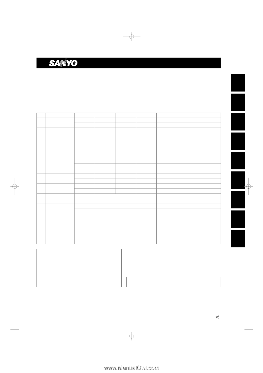
– Split System Heat Pump Air Conditioner –
INSTALLATION
INSTRUCTIONS
Model Combinations
Combine indoor and outdoor units only as listed below.
Indoor Units and Outdoor Units
* When air discharge chamber is installed.
OPERA
TING LIMITS
■
Maximum Conditions
Cooling
/ Heating
Outdoor temperature :
109°F DB
/
65°F WB
Room temperature
:
71°F WB
/
80°F DB
■
Minimum Conditions
Outdoor temperature :
0°F* DB
/
5°F WB
Room temperature
:
57°F WB
/
59°F DB
Units should be installed by licensed contractor according to
local code requirements.
Indoor Unit Type
26
30
36
42
Remarks
X
4-Way Air Discharge
XH2672R
XH3672R
XH4272R
Optional remote controller
Semi-Concealed
XHW2672R
XHW3672R
XHW4272R
with Wired Remote Controller: RCS-TM80BG
KH2672R
KH3072R
KH3672R
Optional remote controller
K
Wall-Mounted
KHS2672R
KHS3072R
KHS3672R
with Wireless Remote Controller: RCS-SH1UA
KHH2672R
Optional remote controller
KHHS2672R
with Wireless Remote Controller: RCS-SH1UA
TH2672R
TH3672R
TH4272R
Optional remote controller
THW2672R
THW3672R
THW4272R
with Wired Remote Controller: RCS-TM80BG
T
Ceiling-Mounted
THH2672R
THH3672R
Unit with Back-up heater
THHW2672R
THHW3672R
Unit with Back-up heater
with Wired Remote Controller: RCS-TM80BG
U
Concealed-Duct
UH2672R
UH3672R
Optional remote controller
UHW2672R
UHW3672R
with Wired Remote Controller: RCS-TM80BG
C
Outdoor Units
CH2672R
CH3072R
CH3672R
CH4272R
H/P
C2672R
C3072R
C3672R
C4272R
S/C
RC
Wired Remote
RCS-SH80UG (Optional part)
(WD)
Controller
RC
Wireless Remote
Built-in type:
RCS-SH80UA.WL (Optional part)
for X and T type Indoor units
(WL)
Controller
External type: RCS-BH80UA.WL (Optional part)
for U type Indoor units
Built-in type:
RCS-SH80UA (Accessory part / Optional part)
for K type Indoor units
Timer Remote
for X, T and U type Indoor units.
TRC
Controller
RCS-TM80BG* (Accessory part / Optional part)
* Timer Remote Controller comes with
Owner’s Manual and Installation Instructions.
SC
System Controller
SHA-KC64UG (Optional part)
SANYO Commercial Solutions
In Canada
A division of SANYO North America Corporation
SANYO Canada Inc.
Cornerstone Business Park
1-300 Applewood Crescent
1062 Thorndale Avenue
Concord, Ontario
Bensenville, IL 60106, U.S.A.
L4K 5C7, Canada
07-115 SSHP_II
5/7/07
3:59 PM
Page a