Sony HDWS280 Product Manual (Operation Manual 1st Edition (Revised 5))
Sony HDWS280 Manual
 |
View all Sony HDWS280 manuals
Add to My Manuals
Save this manual to your list of manuals |
Sony HDWS280 manual content summary:
- Sony HDWS280 | Product Manual (Operation Manual 1st Edition (Revised 5)) - Page 1
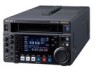
HD DIGITAL VIDEOCASSETTE RECORDER HDW-S280 The supplied CD-ROM includes Operation Manual (English, French, German, and Japanese versions) in PDF format. For details, see "1-3 Using the CD-ROM Manual" on page 12. OPERATION MANUAL [English] 1st Edition (Revised 5) - Sony HDWS280 | Product Manual (Operation Manual 1st Edition (Revised 5)) - Page 2
constitute a risk of electric shock to persons. This symbol is intended to alert the user to the presence of important operating and maintenance (servicing) instructions in the literature accompanying the appliance. WARNING: THIS WARNING IS APPLICABLE FOR USA ONLY. If used in USA, use the UL LISTED - Sony HDWS280 | Product Manual (Operation Manual 1st Edition (Revised 5)) - Page 3
a qualified service personnel. For the customers in the U.S.A. This equipment has been tested and found to comply with the limits for a Class A digital device, if not installed and used in accordance with the instruction manual, may cause harmful interference to radio communications. Operation - Sony HDWS280 | Product Manual (Operation Manual 1st Edition (Revised 5)) - Page 4
1-7-1 Konan, Minato-ku, Tokyo, Japon. Le représentant autorisé pour EMC et la sécurité des produits est Sony Deutschland GmbH, Hedelfinger Strasse 61, 70327 Stuttgart, Allemagne. Pour toute question concernant le service ou la garantie, veuillez consulter les adresses indiquées dans les documents de - Sony HDWS280 | Product Manual (Operation Manual 1st Edition (Revised 5)) - Page 5
Corporation, 1-7-1 Konan, Minato-ku, Tokyo, Japan. Der autorisierte Repräsentant für EMV und Produktsicherheit ist Sony Deutschland GmbH, Hedelfinger Strasse 61, 70327 Stuttgart, Deutschland. Bei jeglichen Angelegenheiten in Bezug auf Kundendienst oder Garantie wenden Sie sich bitte an die in den - Sony HDWS280 | Product Manual (Operation Manual 1st Edition (Revised 5)) - Page 6
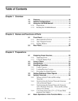
System Configurations 11 1-3 Using the CD-ROM Manual 12 1-3-1 Preparations 12 1-3-2 Reading the CD-ROM Manual 12 Chapter 2 Names and Functions of Parts the Internal Timecode Generator with a Playback Timecode - Timecode Recording during Auto Editing 30 3-6-4 Converting Timecode in 24- or - Sony HDWS280 | Product Manual (Operation Manual 1st Edition (Revised 5)) - Page 7
Stick 38 3-9-1 Notes on "Memory Stick 38 Chapter 4 Recording and Playback 4-1 Recording 40 4-1-1 Preparations for Recording 40 4-1-2 Recording Operation 40 4-2 Back Space Editing 41 4-3 Sequential Recording 41 4-4 Playback 43 4-4-1 Preparations for Playback 43 4-4-2 Playback Operation - Sony HDWS280 | Product Manual (Operation Manual 1st Edition (Revised 5)) - Page 8
Code 54 Chapter 8 UMID Functions 8-1 Overview of UMID Functions 55 8-2 Recording UMIDs 55 8-3 UMID Output and Display 58 8-3-1 UMID Output Settings Warning Messages 82 Moisture Condensation 83 Regular Checks 83 10-6-1 Digital Hours Meter 83 10-6-2 Maintenance Timings 84 10-7 LCD Monitor - Sony HDWS280 | Product Manual (Operation Manual 1st Edition (Revised 5)) - Page 9
For the customers in the U.S.A. and Canada Note (Video set up amount) The video setup amount is set to 0% at the factory. If necessary, you can change the amount using setup menu item 713. For details on setup menu item 713, see page 74. 9 - Sony HDWS280 | Product Manual (Operation Manual 1st Edition (Revised 5)) - Page 10
Chapter 1 Overview 1-1 Features The HDW-S280 is a digital portable videocassette recorder for the HDCAM format. The unit has the SMPTE292M standards and is recorded in HDCAM format. The following input and output signals are supported: • HD-SDI (high-definition serial digital interface) video and - Sony HDWS280 | Product Manual (Operation Manual 1st Edition (Revised 5)) - Page 11
HDCAM Digital cassette HD SDI OUTPUT SDI OUT Digital demodulator AUDIO OUTPUT Analog demodulator Digital modulator Analog modulator HD SDI REMOTE INPUT REMOTE 9P COMPOSITE OUT HDW-S280 DOLBY NR P ROLL ASSEMBLE 59.94i SDI ASMBL CONFI ON RECORDER OFF LTC DF VITC LTC EXT-LTC R-RUN REM:00M TCG - Sony HDWS280 | Product Manual (Operation Manual 1st Edition (Revised 5)) - Page 12
Manual for the HDW-S280 in English, Japanese, French, and German in PDF format. 1-3-1 Preparations The following program must be installed on your computer in order to read the operation manuals can purchase a new one to replace it. Contact your Sony service representative. 12 Using the CD-ROM Manual - Sony HDWS280 | Product Manual (Operation Manual 1st Edition (Revised 5)) - Page 13
7 PHONES jack 8 REC INHI switch and indicator 9 KEY INHI switch HDW-S280 0 Cassette comportment EJECT qa EJECT button PB LEVEL 13 REC LEVEL 13 and REC LEVEL adjustment knobs can be used for controlling four-channel recording level or four-channel playback level if you set thie option with - Sony HDWS280 | Product Manual (Operation Manual 1st Edition (Revised 5)) - Page 14
disabled except those of the STOP and EJECT buttons. When two HDW-S280 units are connected, press this button on the player VTR to 1 BANK 2 MONI R : 2 D-STOP DOLBY NR P ROLL ASSEMBLE 59.94i SDI ASMBL CONFI ON RECORDER OFF LTC DF VITC LTC EXT-LTC R-RUN REM:00M TCG SET HOME 00:00:00:00. DISPLAY - Sony HDWS280 | Product Manual (Operation Manual 1st Edition (Revised 5)) - Page 15
button, you can switch between standby on and standby off mode manually. Tape protection settings are made with setup menu items 500s. record) button Press together with the PLAY button to start recording. When two HDW-S280 units are connected, this button allows you to perform sequential recording - Sony HDWS280 | Product Manual (Operation Manual 1st Edition (Revised 5)) - Page 16
-40 1 23 4 HD INPUT : ANA CH1 IN : -60 CH2 IN : -4 COND OUT : +4 MONI L : 1 BANK 2 MONI R : 2 D-STOP DOLBY NR P ROLL 59.94i SDI ASMBL CONFI ON RECORDER OFF LTC DF VITC LTC EXT-LTC R-RUN REM:00M TCG SET HOME 00:00:00:00. 4 Condition area 5 Format area 6 Timecode setup area 7 Time - Sony HDWS280 | Product Manual (Operation Manual 1st Edition (Revised 5)) - Page 17
of the function menu is set to ON. B Audio level meters Display the recording and playback audio levels of the four audio channels (CH-1 to CH-4). M370. For details on the maintenance menu item M370 refer to the maintenance manual. c Audio data Displays the audio data. INPUT: Input signal selected - Sony HDWS280 | Product Manual (Operation Manual 1st Edition (Revised 5)) - Page 18
data type A Time data type Displays the type of time data displayed in the time data display area. B Drop frame display DF appears when a tape recorded in drop frame mode is played. C Timecode type When VITC is read during playback, VITC is displayed. When LTC is read, LTC is displayed. During - Sony HDWS280 | Product Manual (Operation Manual 1st Edition (Revised 5)) - Page 19
Chapter 2 Names and Functions of Parts Video monitor display 0 -10 -20 -30 -40 1 2 DC-SQ TCR. 00:45. 39. 18* JOG STILL C Superimposed data B Up-converter, down-converter display A Audio level meter When you press the DISPLAY button, the display window changes to the video monitor display. A - Sony HDWS280 | Product Manual (Operation Manual 1st Edition (Revised 5)) - Page 20
Supplying Power" on page 22. e TIME CODE connectors (BNC type) IN: To record a timecode from an external device, input the timecode from the external device. OUT: 9P connector (D-SUB 9-pin) When editing using two HDW-S280 units, connect a 9-pin remote control cable (not supplied) to this connector - Sony HDWS280 | Product Manual (Operation Manual 1st Edition (Revised 5)) - Page 21
of Parts each unit. For editing using this unit and an HDCAM VTR, connect the external equipment. j AUDIO MONITOR OUTPUT connectors two HDW-S280 units, connect a cable between these connectors on the recorder VTR and the HD SDI OUTPUT connectors on the player VTR. o SDI OUT (serial digital interface - Sony HDWS280 | Product Manual (Operation Manual 1st Edition (Revised 5)) - Page 22
recording time, and the BP-L80S provides up to 55 minutes. For details on charging battery packs, refer to the operation manual for the battery charger. Applicable battery packs For safety, use only the Sony battery charger. Refer to the operating instructions for your battery charger for more - Sony HDWS280 | Product Manual (Operation Manual 1st Edition (Revised 5)) - Page 23
to the side panel of this unit and attach the battery pack in it. For details on attaching the BKP-L551, refer to the installation manual for the BKP-L551. 1 Remove the two screws on the side panel. BP-GL65/GL95 4 Slide the BP-GL65/GL95 as shown below so that - Sony HDWS280 | Product Manual (Operation Manual 1st Edition (Revised 5)) - Page 24
Chapter 3 Preparations 3-2 Using a Stand Placing the unit using a stand 1 Remove the stand from the clamps and turn it, as indicated by the arrow. Stand Clamps 2 Push the stand in, as indicated by the arrow. Be sure to push it to the end. Replacing the stand Pull the stand out, turn it in the - Sony HDWS280 | Product Manual (Operation Manual 1st Edition (Revised 5)) - Page 25
3 Preparations 3-3 Connections For editing using two HDW-S280 units, connect them as shown below. Player REF. INPUT REMOTE 9P (SUPER) AUDIO INPUT AUDIO OUTPUT 1 2 1 2 AUDIO MONITOR OUTPUT R L Recorder VTR 9-pin remote control cable (not supplied) -AC IN POWER ON - AC IN REMOTE DC IN - Sony HDWS280 | Product Manual (Operation Manual 1st Edition (Revised 5)) - Page 26
3-4 Handling Cassettes 3-4-1 Usable Cassettes For recording and playback, you can use an HDCAM S cassette such as a BCT-6HD/ cassette. 3-4-3 Preventing Accidental Erasures To make it impossible to accidentally erase or record over the contents of a cassette, press in the erasure prevention plug. - Sony HDWS280 | Product Manual (Operation Manual 1st Edition (Revised 5)) - Page 27
, jog mode, shuttle mode, stop mode) ASSEMBLE: Assemble edit mode (ASSEMBLE on the HOME page of the function menu is set to ON.) REC: Recording If the signal selected on the menu is not being input The servo reference video signal and internal reference signal generator synchronize as follows. When - Sony HDWS280 | Product Manual (Operation Manual 1st Edition (Revised 5)) - Page 28
Recording Timecode For setting the timecode, set TCG on the P4 TC page of the function menu to INT and PRST/RGN to PRESET. HDW-S280 1 BANK 2 MONI R : 2 D-STOP DOLBY NR P ROLL ASSEMBLE 59.94i SDI ASMBL CONFI ON RECORDER OFF LTC DF VITC LTC EXT-LTC R-RUN REM:00M TCG SET HOME 00:00:00:00. DISPLAY - Sony HDWS280 | Product Manual (Operation Manual 1st Edition (Revised 5)) - Page 29
time. 3 Press the SET function button at the instant when the current time matches the displayed timecode. Setting user bits You can record up to 8 hexadecimal digits of information (date, time, event number, etc.) on the timecode track. Select UB by pressing the CTL/TC function button in step - Sony HDWS280 | Product Manual (Operation Manual 1st Edition (Revised 5)) - Page 30
the P4 TC page: LTC or VITC In automatic editing, timecodes are recorded by using the output of the internal timecode generator, which has been synchronized for 25-frame mode. It is also possible to have the timecodes recorded in 25frame mode converted to those for 24-frame mode during playback. - Sony HDWS280 | Product Manual (Operation Manual 1st Edition (Revised 5)) - Page 31
details on settings on the P7 page, refer to the maintenance manual. 3-7-1 Configuration of the Function Menu HOME F1 CHARACTR ON/OFF F2 PRST/RGN PRESET/LTC/ VITC RUN FREE/REC DF DF/NDF P5 EDIT R/P RECORDER/ PLAYER IN Not displayed/ Lit/Flashinga) DELETE Not displayed/ Lit/Flashinga) OUT - Sony HDWS280 | Product Manual (Operation Manual 1st Edition (Revised 5)) - Page 32
being played back or recorded, as calculated from a count of CTL signals recorded on the tape. digital video processor, using the setup menu. Note When controlling the unit with the HKDV-900, set to MENU. VIDEO Sets the HD/SD video signal output level (−∞ to +3 dB). PRESET: Regardless of manually - Sony HDWS280 | Product Manual (Operation Manual 1st Edition (Revised 5)) - Page 33
SD output signal. PRESET: Regardless of manually set values, the level is set to the standard value. Manual setting: With the displayed setting flashing, to the REF INPUT connector as the reference signal. During recording, input digital audio signals and video signals must be synchronized with this - Sony HDWS280 | Product Manual (Operation Manual 1st Edition (Revised 5)) - Page 34
regardless of the operating mode of this unit. REC: The timecode increases during recording only. If you select this mode, you should also set TCG to Item R/P IN Setting Selects which VTR to be controlled (player or recorder) when two VTRs are connected, the VTR connected to the REMOTE 9P connector is - Sony HDWS280 | Product Manual (Operation Manual 1st Edition (Revised 5)) - Page 35
button after recording a stop code. Returns to the P6 OTHER page. 3-7-3 Basic Operations This section describes the basic operations of the function menu. Operation of some items may differ from the basic ones, which are described in the corresponding sections. MULTI CONTROL knob HDW-S280 EJECT - Sony HDWS280 | Product Manual (Operation Manual 1st Edition (Revised 5)) - Page 36
3 (for 59.94i mode) or fields 1, 3, 5 and 7 (for 50i mode) "*": Fields 2 and 4 (for 59.94i mode) or fields 2, 4, 6 and 8 (for 50i mode) e Selection of recorder/player The indication changes as follows, according to the setting for R/P on the P5 EDIT page of the function menu: P: PLAYER is selected - Sony HDWS280 | Product Manual (Operation Manual 1st Edition (Revised 5)) - Page 37
Fast forward mode Rewind mode Preroll mode Play mode (servo unlocked) Play mode (servo locked) Play mode (standby) Record mode (servo unlocked) Record mode (servo locked) Record mode (standby) Still picture in jog mode Jog in forward direction Jog in reverse direction Shuttle mode Automatic editing - Sony HDWS280 | Product Manual (Operation Manual 1st Edition (Revised 5)) - Page 38
share data among cameras. Inserting a " will Sony be liable for any loss of data. • Unauthorized recording may recording medium with a data capacity that exceeds that of a floppy disk. "Memory Stick" is specially designed for exchanging and sharing digital products.1) The HDW-S280 is not compliant - Sony HDWS280 | Product Manual (Operation Manual 1st Edition (Revised 5)) - Page 39
not use a "Memory Stick Duo" alone with the HDW-S280. To use a "Memory Stick Duo" with this camera, be sure to attach it to an optional Memory Stick Terminal Write-protect tab Chapter 3 Preparations Labeling position • You cannot record or erase data when the write-protect tab on the "Memory Stick - Sony HDWS280 | Product Manual (Operation Manual 1st Edition (Revised 5)) - Page 40
and Playback Chapter Chapter 4 Recording and Playback 4-1 Recording This section describes recording for external input signals. Note When two HDW-S280 units are connected, press the REMOTE buttons on both VTRs so that they are not lit. channels to be controlled with the REC LEVEL adjustment - Sony HDWS280 | Product Manual (Operation Manual 1st Edition (Revised 5)) - Page 41
with no noise or breakup between scenes (back space editing). Proceed as follows. When you connect two HDW-S280 units as shown below, you can perform sequential recording from one unit to another. HDW-S280 EJECT PB LEVEL 13 REC LEVEL 13 24 24 R/P LEVEL CTL VAR LEVEL PRESET PHONES REC INHI - Sony HDWS280 | Product Manual (Operation Manual 1st Edition (Revised 5)) - Page 42
. When the recording VTR is switched, recording is performed on the both VTRs for two minutes. Starting VTR 3 Not lit HDW-S280 EJECT PB LEVEL during recording • If the cassette is not exchanged when the cassette mark flashes, even though setup menu item 014 is set to REPL (Manual Cassette - Sony HDWS280 | Product Manual (Operation Manual 1st Edition (Revised 5)) - Page 43
Chapter 4 Recording and Playback 4-4 Playback This section describes playback of tapes. Note When two HDW-S280 units are connected, press the menu depending on the format of the cassette to be played. To play an HDCAM cassette Select the down-convert mode with setup menu item 930. For details on - Sony HDWS280 | Product Manual (Operation Manual 1st Edition (Revised 5)) - Page 44
jog mode. For details on setup menu item 101, see page 66. HDW-S280 EJECT PB LEVEL 13 REC LEVEL 13 24 24 R/P LEVEL CTL VAR 1 BANK 2 MONI R : 2 D-STOP DOLBY NR P ROLL ASSEMBLE 59.94i SDI ASMBL CONFI ON RECORDER OFF LTC DF VITC LTC EXT-LTC R-RUN REM:00M TCG SET HOME 00:00:00:00. DISPLAY - Sony HDWS280 | Product Manual (Operation Manual 1st Edition (Revised 5)) - Page 45
via the REMOTE 9P connector. Sequence of editing operations The sequence of editing operations using two HDW-S280 when units is as shown below. Set the assemble edit mode. r Set edit points on the recorder VTR and player VTR. r Preview between the edit points. r Modify the edit points, if necessary - Sony HDWS280 | Product Manual (Operation Manual 1st Edition (Revised 5)) - Page 46
points Function buttons Menu display area Time data display area HDW-S280 EJECT PB LEVEL 13 REC LEVEL 13 24 24 R/P function button on the P5 EDIT page of the function menu to select a VTR (PLAYER or RECORDER) for checking the set edit points. 2 Press the IN function button to display the data - Sony HDWS280 | Product Manual (Operation Manual 1st Edition (Revised 5)) - Page 47
on the P5 EDIT page of the function menu to set a VTR (PLAYER or RECORDER) for deleting the edit points. 2 To delete the IN point, press the DELETE the procedure below. Function buttons Menu display area Time data display area HDW-S280 EJECT PB LEVEL 13 REC LEVEL 13 24 24 R/P LEVEL CTL VAR - Sony HDWS280 | Product Manual (Operation Manual 1st Edition (Revised 5)) - Page 48
with the IN or OUT function button on the P5 EDIT page of the function menu. Monitor output During a preview, on a monitor connected to the recorder you can monitor the following video and audio: • From the preroll point to the IN point, you can monitor the playback from the - Sony HDWS280 | Product Manual (Operation Manual 1st Edition (Revised 5)) - Page 49
VTR to E-E mode, in which the player video and audio signals are output to the monitor. IN point OUT point PB (Recorder) E-E (Player) E-E (Player) Starting automatic editing When you have set the edit points, the AUTOEDIT indicator in the menu display area starts flashing. Press the AUTOEDIT - Sony HDWS280 | Product Manual (Operation Manual 1st Edition (Revised 5)) - Page 50
Timecode" on page 28. 3 With setup menu item 615, set the number of seconds before the timecode value set in step 2 from which you want recording to start (10 to 30 seconds). For details on setup menu item 615, see page 71. 4 Hold down the REC button and press the AUTO - Sony HDWS280 | Product Manual (Operation Manual 1st Edition (Revised 5)) - Page 51
record shot marks or use shot marks recorded with HDCAM comcorders or Betacam SX camcorders (shot mark function). The shot mark function enables quick access to the marked points, for efficient editing. When shot data are recorded number Time Shot number Camera ID Recorded timecode The content of - Sony HDWS280 | Product Manual (Operation Manual 1st Edition (Revised 5)) - Page 52
is as shown below. This section describes the operations for detecting or recording stop codes. 7-2-1 Detecting the Stop Code Detecting the stop code Function buttons Menu display area Condition area HDW-S280 EJECT Tape direction Stop position SOM Stop code Adjustable 20 frames 3 seconds - Sony HDWS280 | Product Manual (Operation Manual 1st Edition (Revised 5)) - Page 53
page 67. Tape running direction 0 frame 30 frames SOM Stop code Stop position adjustable range 7-2-2 Recording the Stop Code Recording the stop code Proceed as follows. Function button Menu display area HDW-S280 EJECT PB LEVEL 13 REC LEVEL 13 24 24 R/P LEVEL CTL VAR LEVEL PRESET PHONES - Sony HDWS280 | Product Manual (Operation Manual 1st Edition (Revised 5)) - Page 54
, and playback starts. If the tape stops at the position where the stop code was recorded, the erasure operation must be performed again. Erasing the stop code Proceed as follows. Function button Menu display area HDW-S280 EJECT PB LEVEL 13 REC LEVEL 13 24 24 R/P LEVEL CTL VAR LEVEL PRESET - Sony HDWS280 | Product Manual (Operation Manual 1st Edition (Revised 5)) - Page 55
Material Identifier) is a type of meta-data in video and audio materials. It has been internationally standardized in SMPTE Standard 330M. This unit supports recording and generation of UMIDs. UMID is made up of a section called the Basic section and a section called the Source Pack section. The - Sony HDWS280 | Product Manual (Operation Manual 1st Edition (Revised 5)) - Page 56
*USER - XXXX - YYYY - ABCD Function buttons Menu display area HDW-S280 EJECT PB LEVEL 13 REC LEVEL 13 24 24 R/P LEVEL CTL VAR BANK 2 MONI R : 2 D-STOP DOLBY NR P ROLL ASSEMBLE 59.94i SDI ASMBL CONFI ON RECORDER OFF LTC DF VITC LTC EXT-LTC R-RUN REM:00M TCG SET HOME 00:00:00:00. DISPLAY - Sony HDWS280 | Product Manual (Operation Manual 1st Edition (Revised 5)) - Page 57
the SET function button. The setting is registered. For details on the error logger, refer to the Maintenance Manual Volume 1. 2 Press the SETTING function button PREVIOUS NEXT OFF ON EXIT 00:26:23:09 ERR LOG TAPE mark appears before OFFSET TO UTC. Chapter 8 UMID Functions 57 Recording UMIDs - Sony HDWS280 | Product Manual (Operation Manual 1st Edition (Revised 5)) - Page 58
choose to output UMIDs. Make these settings using setup menu item 651. For details on setup menu item 651, see page 72. 8-3-2 UMID Display During recording and playback, UMID data appear in the time data display area of the display window and on the video monitor screen. Displaying the UMID Press - Sony HDWS280 | Product Manual (Operation Manual 1st Edition (Revised 5)) - Page 59
data from a Sensor. R is shown for position data from the recording device (Recorder), and T is shown for Target position data. + (2nd character): between Y and D): Displayed when a support apparatus was used. A space (blank) is displayed when no support apparatus was used. f LONGITUDE Following W - Sony HDWS280 | Product Manual (Operation Manual 1st Edition (Revised 5)) - Page 60
manual In this manual, both the basic setup menu items and extended setup menu items are also referred to simply as setup menu items or menu items. 9-2-1 Displaying Setup Menus MENU button HDW-S280 NR P ROLL ASSEMBLE 59.94i SDI ASMBL CONFI ON RECORDER OFF LTC DF VITC LTC EXT-LTC R-RUN REM:00M - Sony HDWS280 | Product Manual (Operation Manual 1st Edition (Revised 5)) - Page 61
menu. RETURN 9-2-2 Setting Setup Menu Function buttons MENU button HDW-S280 EJECT PB LEVEL 13 REC LEVEL 13 24 24 R/P LEVEL 1 BANK 2 MONI R : 2 D-STOP DOLBY NR P ROLL ASSEMBLE 59.94i SDI ASMBL CONFI ON RECORDER OFF LTC DF VITC LTC EXT-LTC R-RUN REM:00M TCG SET 00:26:23:09 HOME 001: P- - Sony HDWS280 | Product Manual (Operation Manual 1st Edition (Revised 5)) - Page 62
Switching the system frequency (menu item 013) To switch the system frequency, proceed as follows. Note • Before carrying out this operation, consult the person responsible for system installation. • When the unit is used in 50i mode, only an analog tape can be played back in the simple playback - Sony HDWS280 | Product Manual (Operation Manual 1st Edition (Revised 5)) - Page 63
CTL count in 12-hour mode or 24-hour mode. [+-12H]: 12-hour mode 24H: 24-hour mode For recorder-player editing with only one monitor connected to the recorder, determines whether the recorder is forced into E-E mode when R/P on the P5 EDIT page of the function menu is set to PLAYER to - Sony HDWS280 | Product Manual (Operation Manual 1st Edition (Revised 5)) - Page 64
back in the simple playback mode. 014 SEQUENTIAL RECORD Selects the method for sequential recording using two HDW-S280 units. MODE [OFF]: No sequential recording REPL: For one time sequential recording. Every time a sequential recording ends, replace a cassette. OVER: For repeated sequential - Sony HDWS280 | Product Manual (Operation Manual 1st Edition (Revised 5)) - Page 65
Item Item name number B12 SAVE SETUP BANK 2 B20 RESET CURRENT SETUP Settings Set to ON to save current active menu settings to menu bank 2. Set to ON to reset current active menu settings to factory default values. a) To set items 002, 003, 009, and 011, watch the monitor and adjust to the - Sony HDWS280 | Product Manual (Operation Manual 1st Edition (Revised 5)) - Page 66
Select how the unit enters the search mode. SEARCH DIAL ENABLE DIAL: Turning the search dial switches to search mode at all times except during recording/editing. [KEY]: The JOG/SHUTTLE button must be pressed to switch to search mode. 104 AUDIO MUTING TIME Select the length of time for which - Sony HDWS280 | Product Manual (Operation Manual 1st Edition (Revised 5)) - Page 67
DIAL [OFF]: Disabled the tracking control ON: Enabled the tracking control during playback 138 STOP CODE FUNCTION Set for detection of the stop code, and recording to a tape. Note This is enabled in 59.94i, 29.97PsF mode only. Sub-item 1 STOP ADJUST Adjust the position to stop the tape when - Sony HDWS280 | Product Manual (Operation Manual 1st Edition (Revised 5)) - Page 68
reference signal is forced to be an external reference video input. For two-VTR editing, set when this unit is used as the recorder. Selects the operation if the recorder was not synchronized in time. OFF: Editing is not carried out, and the unit stops. [ON]: The editing is automatically retried (up - Sony HDWS280 | Product Manual (Operation Manual 1st Edition (Revised 5)) - Page 69
Items 400 to 499: Settings for preroll Item Item name number Settings 401 FUNCTION MODE AFTER Select the state that the unit goes into after a cuing-up operation. CUEUP [STOP]: Stop (the stop mode) STILL: Still playback (in search mode) Note When controlling this unit from an editor with - Sony HDWS280 | Product Manual (Operation Manual 1st Edition (Revised 5)) - Page 70
T or t function button. When you select all digits, set the SET function button again. The ID code is stored and the ID code setting mode is terminated. Select whether or not to record the ID code set using item 603 in the user bits. [OFF]: Record the normal data in the user bits - Sony HDWS280 | Product Manual (Operation Manual 1st Edition (Revised 5)) - Page 71
on the tape. MANU: Regardless of whether this unit is the recorder or player, the timecode generator operates in accordance with the settings of user starting timecode digit by digit using the F3 (C) button and F4 (c) buttons for digit selection. When all required digits have been set correctly - Sony HDWS280 | Product Manual (Operation Manual 1st Edition (Revised 5)) - Page 72
the user starting timecode digit by digit using the F3 (C) button and F4 (c) buttons for digit selection. When all required digits have been set correctly, Even if EXTENDED is selected, Basic UMID is output if Basic UMID is recorded on the tape being played back. UMID HD VANC LINE Specify the HD - Sony HDWS280 | Product Manual (Operation Manual 1st Edition (Revised 5)) - Page 73
the edge subcarrier reducer (ESR) is automatically switched on or off according to the VTR operation. When playing an SD tape with a Non-Standard signal recorded, for example, if the color edges are not as good as with a proper signal, the ESR can be forced on. This item makes this selection - Sony HDWS280 | Product Manual (Operation Manual 1st Edition (Revised 5)) - Page 74
adjust the Y/C delay. 0 to [800H] to FFFH 726a) H BLANKING WIDTH Select the horizontal blanking width of the video output signal. [NARROW]: Digital blanking (narrow) WIDE: Analog blanking (wide) When WIDE is selected, the horizontal blanking width complies with RS170A, and normally the blanking is - Sony HDWS280 | Product Manual (Operation Manual 1st Edition (Revised 5)) - Page 75
FULL: Muted in shuttle mode. SLOW: Muted, with the speed less than ±0.2 time normal playback. 807 AUDIO OUTPUT PHASE Select the output timing of digital audio playback signals (HD SDI, and SDI only). The reference position corresponds to a setting for 80H; when the setting is less than 80H, the - Sony HDWS280 | Product Manual (Operation Manual 1st Edition (Revised 5)) - Page 76
digital audio channel recorded on cue channel. OFF: No recording CH1+2: Recording audio channels 1 and 2 CH3+4: Recording audio channels 3 and 4 [CH1]: Recording audio channel 1 CH2: Recording fast forward or rewind mode if the playback format is HDCAM or Betacam SX. OFF: The playback sound is not - Sony HDWS280 | Product Manual (Operation Manual 1st Edition (Revised 5)) - Page 77
Items 900 to 999: Settings for digital processing Item Item name number Settings 901 VIDEO the 16:9/Squeeze identification signal specified by ARIB TR-B17 to the downconverted SD output when an HDCAM tape is played. When an SD tape is played, the 16:9/Squeeze identification signal is detected, - Sony HDWS280 | Product Manual (Operation Manual 1st Edition (Revised 5)) - Page 78
Item Item name number Settings 943 CROSS COLOR CRISP Set the cross color crisp level for down-converter output. 0 to [4] to FH 950 UP CONVERTER MODE (UC) Select the up-converter mode. [CROP]: Select the edge-crop mode. L-BOX: Select the letter box mode. SQUEZ: Select the squeeze mode. - Sony HDWS280 | Product Manual (Operation Manual 1st Edition (Revised 5)) - Page 79
job should always be entrusted to a technician who has undergone service training. For details, refer to the Installation Manual. 10-2 Head Cleaning To clean the video heads and audio heads, always use the special-purpose Sony BCT-HD12CL cleaning cassette. If you insert the cleaning cassette, it - Sony HDWS280 | Product Manual (Operation Manual 1st Edition (Revised 5)) - Page 80
problem is detected, displays an error message in the time data display and on the monitor. If an error message appears, contact your Sony service 03 Message REEL TROUBLE REEL TROUBLE REEL TROUBLE 04 REEL TROUBLE 05 REEL TROUBLE 06 TAPE TENSION 07 CAPSTAN TROUBLE 08 DRUM TROUBLE 09 TH/UNTH MOTOR - Sony HDWS280 | Product Manual (Operation Manual 1st Edition (Revised 5)) - Page 81
Code Message 96 SY NV-RAM ERROR 97 SV NV-RAM ERROR 98 NV-RAM ERROR 99 INTERNAL I/F 2 Description Abnormality has been detected in the operation of an NV-RAM (on SY-320 board) for the system control system. Abnormality has been detected in the operation of an NV-RAM (on SV-225 board) for the servo - Sony HDWS280 | Product Manual (Operation Manual 1st Edition (Revised 5)) - Page 82
MUTING NO RF AU MUTING AUX DATA AU MUTING Description No reference signal is input. Capstan servo lock is released during playback, recording or editing. No video signal is detected during recording. Phase difference of the video input signal and reference signal exceeds the allowable range during - Sony HDWS280 | Product Manual (Operation Manual 1st Edition (Revised 5)) - Page 83
digital hours meter can display seven items of information, in corresponding display modes, about the operational history of the unit. Use it as a guide of hours the unit has been in fast forward, rewind, playback, search, recording or editing (except for stop and still) mode in units of 1 hour. - Sony HDWS280 | Product Manual (Operation Manual 1st Edition (Revised 5)) - Page 84
digital hours meter Function buttons MENU button HDW-S280 2 MONI R : 2 D-STOP DOLBY NR P ROLL ASSEMBLE 59.94i SDI ASMBL CONFI ON RECORDER OFF LTC DF VITC LTC EXT-LTC R-RUN REM:00M TCG SET HOME 00:00:00:00 Use the following table as a timing guide for checking and replacing components of the - Sony HDWS280 | Product Manual (Operation Manual 1st Edition (Revised 5)) - Page 85
off. In addition, over a long period of use, because of the physical characteristics of the liquid crystal display, such "stuck" pixels may appear spontaneously. These problems have been kept to the absolute minimum, but are an unavoidable characteristic of liquid crystal technology. 85 LCD Monitor - Sony HDWS280 | Product Manual (Operation Manual 1st Edition (Revised 5)) - Page 86
(525/59.94) 101.5 mm/s (625/50) HDCAM record/playback time 40 minutes with BCT-40HD (59.94i, Digital video system Digital video signal format Sampling frequency HD Y: 74.25 MHz R-Y/B-Y: 37.125 MHz SD Y: 13.5 MHz R-Y/B-Y: 6.75 MHz Quantization 8 bits/sample Compression Coefficient recording - Sony HDWS280 | Product Manual (Operation Manual 1st Edition (Revised 5)) - Page 87
) 1% or less Differential gain 2% or less Differential phase 2° or less Y/C delay 20 ns or less Digital Audio (CH1 to CH4) Frequency response 20 Hz to 20 kHz +0.5 dB/ −1.0 dB (Standardize at 1 kHz) Dynamic range HDCAM 90 dB or more (at 1 kHz, emphasis on) SX 88 dB or more (at 1 kHz - Sony HDWS280 | Product Manual (Operation Manual 1st Edition (Revised 5)) - Page 88
less less Note The AFM function is not supported. Processor adjustment range Video level Chroma level input and for through output to a monitor) Serial digital (1.485 Gbits/s) SMPTE 292M REF. INPUT BNC (2 Manual Japanese version (1) English version (1) CD-ROM manual (1) Installation Manual - Sony HDWS280 | Product Manual (Operation Manual 1st Edition (Revised 5)) - Page 89
powered off. Notes • Always make a test recording, and verify that it was recorded successfully. SONY WILL NOT BE LIABLE FOR DAMAGES OF ANY the DC values. HD: HDSDI output during HDCAM playback DC: Down-converted SD (D1 SDI/COMPOSITE) output during HDCAM playback SD: SD (D1 SDI/COMPOSITE) output - Sony HDWS280 | Product Manual (Operation Manual 1st Edition (Revised 5)) - Page 90
on the maintenance menu, refer to the maintenance manual. Item No. Item Name M3 M3A: OUTPUT phase of the reference signal when up-converted. Compatibility of playback tape formats Playback tape format HDCAM 23.98PsF 24PsF 25PsF 50i 29.97PsF 59.94i 30PsF 60i Betacam SX 50i (PAL) 59 - Sony HDWS280 | Product Manual (Operation Manual 1st Edition (Revised 5)) - Page 91
21 Condition area 17 CONFI display 18 Connections 25 D DATA/EMPH indicator 17 DC IN 12V connector 20 DC operation display 17 DC power 22 Digital hours meter 83 Displaying 84 Direct jog/shuttle mode 44 DISPLAY button 14 Display window 14, 16 Operation display 16 Video monitor display 19 Drop - Sony HDWS280 | Product Manual (Operation Manual 1st Edition (Revised 5)) - Page 92
14 REMOTE connector 20 RESET button 14 REW button 15 S SDI input display 18 SDI OUT connector 21 Search dial 16 Search indicator 16 Sequential recording 41 Servo indicator 15 Setup menu 60 Setup menus Basic detup menu 63 Configuration 60 Displaying 60 Extended setup menu 66 Menu bank 62 Operations - Sony HDWS280 | Product Manual (Operation Manual 1st Edition (Revised 5)) - Page 93
Corporation and is intended solely for use by the purchasers of the equipment described in this manual. Sony Corporation expressly prohibits the duplication of any portion of this manual or the use thereof for any purpose other than the operation or maintenance of the equipment described in this - Sony HDWS280 | Product Manual (Operation Manual 1st Edition (Revised 5)) - Page 94
HDW-S280 (SY) 3-857-685-06 (1) Sony Corporation Printed in Japan 2008.12 13 © 2004
-
 1
1 -
 2
2 -
 3
3 -
 4
4 -
 5
5 -
 6
6 -
 7
7 -
8
-
9
-
10
-
11
-
12
-
13
-
14
-
15
-
16
-
17
-
18
-
19
-
20
-
21
-
22
-
23
-
24
-
25
-
26
-
27
-
28
-
29
-
30
-
31
-
32
-
33
-
34
-
35
-
36
-
37
-
38
-
39
-
40
-
41
-
42
-
43
-
44
-
45
-
46
-
47
-
48
-
49
-
50
-
51
-
52
-
53
-
54
-
55
-
56
-
57
-
58
-
59
-
60
-
61
-
62
-
63
-
64
-
65
-
66
-
67
-
68
-
69
-
70
-
71
-
72
-
73
-
74
-
75
-
76
-
77
-
78
-
79
-
80
-
81
-
82
-
83
-
84
-
85
-
86
-
87
-
88
-
89
-
90
-
91
-
92
-
93
-
94
 |
 |

HD DIGITAL VIDEOCASSETTE RECORDER
HDW-S280
OPERATION MANUAL
[English]
1st Edition (Revised 5)
The supplied CD-ROM includes Operation Manual (English, French, German, and
Japanese versions) in PDF format.
For details, see “1-3 Using the CD-ROM Manual”
on page 12.