Sony HDWS280 Product Manual (Operation Manual 1st Edition (Revised 5)) - Page 21
AUDIO MONITOR OUTPUT connectors XLR - hdw s280 hdcam
 |
View all Sony HDWS280 manuals
Add to My Manuals
Save this manual to your list of manuals |
Page 21 highlights
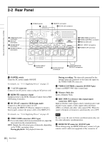
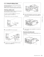
Chapter 2 Names and Functions of Parts each unit. For editing using this unit and an HDCAM VTR, connect the external equipment. j AUDIO MONITOR OUTPUT connectors (XLR 3-pin, male) Output the audio signals of the channels selected with the MONITR L and MONITR R on the P3 AUDIO page of the function menu. For details on the MONITR L and MONITR R settings, see "3-7 Basic Operations of the Function Menu" on page 31. k AUDIO OUTPUT connectors (XLR 3-pin, male) Output the analog audio signals of the channels selected with setup menu item 824. For details on setup menu item 824, see page 76. l AUDIO INPUT connectors (XLR 3-pin, female) Input the analog audio signals. m HD SDI (high-definition serial digital interface) OUTPUT connectors (BNC type) Output the HD-SDI format video/audio signal. When editing with two HDW-S280 units, connect a cable between these connectors on the player VTR and the HD SDI INPUT connectors on the recorder VTR. You can superimpose timecodes, menu settings, error messages, or other information on the output of these connectors with the setting for CHARACTR on the HOME page of the function menu or with the setting for setup menu item 028. You can always disable to superimpose the data independent of the setting for CHARACTR with the setting for setup menu item 028. For details on CHARACTR setting, see "3-7 Basic Operations of the Function Menu" on page 31. For details on the setup menu item 028, see page 64. n HD SDI (high-definition serial digital interface) INPUT connectors (BNC type) Input the HD-SDI format video/audio signal. When editing with two HDW-S280 units, connect a cable between these connectors on the recorder VTR and the HD SDI OUTPUT connectors on the player VTR. o SDI OUT (serial digital interface output) connectors (BNC type) Output a D-1 format video/audio signal. The same signals are output from the left and right connectors. You can superimpose timecode, menu settings, or error messages on the output of the 2(SUPER) connector when CHARACTR on the HOME page of the function menu is set to ON. For details on CHARACTR setting, see "3-7 Basic Operations of the Function Menu" on page 31. p COMPOSITE OUT (analog composite video output) connectors (BNC type) Output analog composite video signals. You can superimpose timecodes, menu settings, or error messages on the output of the 2 (SUPER) connector when CHARACTR on the HOME page of the function menu is set to ON. For details on the CHARACTR setting, see "3-7 Basic Operations of the Function Menu" on page 31. 21 Rear Panel
-
 1
1 -
2
-
3
-
4
-
5
-
6
-
7
-
8
-
9
-
10
-
11
-
12
-
13
-
14
-
15
-
 16
16 -
 17
17 -
 18
18 -
 19
19 -
 20
20 -
 21
21 -
 22
22 -
 23
23 -
 24
24 -
 25
25 -
 26
26 -
27
-
28
-
29
-
30
-
31
-
32
-
33
-
34
-
35
-
36
-
37
-
38
-
39
-
40
-
41
-
42
-
43
-
44
-
45
-
46
-
47
-
48
-
49
-
50
-
51
-
52
-
53
-
54
-
55
-
56
-
57
-
58
-
59
-
60
-
61
-
62
-
63
-
64
-
65
-
66
-
67
-
68
-
69
-
70
-
71
-
72
-
73
-
74
-
75
-
76
-
77
-
78
-
79
-
80
-
81
-
82
-
83
-
84
-
85
-
86
-
87
-
88
-
89
-
90
-
91
-
92
-
93
-
94
 |
 |