Sony HDWS280 Product Manual (Operation Manual 1st Edition (Revised 5)) - Page 13
Names and Functions of, Parts
 |
View all Sony HDWS280 manuals
Add to My Manuals
Save this manual to your list of manuals |
Page 13 highlights
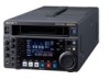
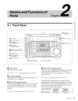
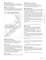
Names and Functions of Parts 2 Chapter Chapter 2 Names and Functions of Parts 2-1 Front Panel 1 Power switch 2 AC power indicator 3 PB LEVEL adjustment knobs 4 REC LEVEL adjustment knobs 5 R/P LEVEL CTL switch 6 LEVEL adjustment knob 7 PHONES jack 8 REC INHI switch and indicator 9 KEY INHI switch HDW-S280 0 Cassette comportment EJECT qa EJECT button PB LEVEL 13 REC LEVEL 13 24 24 R/P LEVEL CTL VAR LEVEL PRESET PHONES REC INHI ON OFF KEY INHI ON OFF SHIFT PAGE HOME CHARACTR ON PB/EE PB CONFI ENABLE CTL/TC TC EMPH EMPH EMPH EMPH 0 0 -10 -10 -20 -20 -30 -30 -40 -40 1 23 4 HD INPUT : ANA CH1 IN : -60 CH2 IN : -4 COND OUT : +4 MONI L : 1 BANK 2 MONI R : 2 D-STOP DOLBY NR P ROLL ASSEMBLE 59.94i SDI ASMBL CONFI ON RECORDER OFF LTC DF VITC LTC EXT-LTC R-RUN REM:00M TCG SET HOME 00:00:00:00. DISPLAY MULTI CONTROL REMOTE MENU RESET PUSH PITCH CTL JOG/SHUTTLE PREROLL qs REMOTE button REW PLAY F FWD STOP REC PAUSE STANDBY Menu operation section Tape transport section a Power switch Turns the unit ON and OFF. For details, see "3-1-1 Supplying Power" on page 22. b AC power indicator Lights while the POWER switch on the rear panel is set to ON and AC power is supplied. c PB LEVEL adjustment knobs Adjust the audio playback level by channel for channels 1 to 4 when the R/P LEVEL CTL switch is set to VAR. Which channels can be adjusted is set with setup menu item 826. For details on setup menu item 826, see page 76. d REC LEVEL adjustment knobs Adjust the audio recording level by channel for audio input to this unit when the R/P LEVEL CTL switch is set to VAR. Which channels can be adjusted is set with setup menu item 826. For details on setup menu item 826, see page 76. The PB LEVEL adjustment knobs and REC LEVEL adjustment knobs can be used for controlling four-channel recording level or four-channel playback level if you set thie option with setup menu item 826. In this case, each knob controls channel indicated below. Adjustment knob REC LEVEL 1 Recording channel Channel 1 Playback channel Channel 3 13 Front Panel
-
 1
1 -
2
-
3
-
4
-
5
-
6
-
7
-
 8
8 -
 9
9 -
 10
10 -
 11
11 -
 12
12 -
 13
13 -
 14
14 -
 15
15 -
 16
16 -
 17
17 -
 18
18 -
19
-
20
-
21
-
22
-
23
-
24
-
25
-
26
-
27
-
28
-
29
-
30
-
31
-
32
-
33
-
34
-
35
-
36
-
37
-
38
-
39
-
40
-
41
-
42
-
43
-
44
-
45
-
46
-
47
-
48
-
49
-
50
-
51
-
52
-
53
-
54
-
55
-
56
-
57
-
58
-
59
-
60
-
61
-
62
-
63
-
64
-
65
-
66
-
67
-
68
-
69
-
70
-
71
-
72
-
73
-
74
-
75
-
76
-
77
-
78
-
79
-
80
-
81
-
82
-
83
-
84
-
85
-
86
-
87
-
88
-
89
-
90
-
91
-
92
-
93
-
94
 |
 |
