Sony HDWS280 Product Manual (Operation Manual 1st Edition (Revised 5)) - Page 84
Maintenance Timings
 |
View all Sony HDWS280 manuals
Add to My Manuals
Save this manual to your list of manuals |
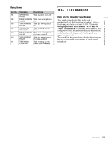
Page 84 highlights
Chapter 10 Maintenance and Inspection Displaying the digital hours meter Function buttons MENU button HDW-S280 EJECT PB LEVEL 13 REC LEVEL 13 24 24 R/P LEVEL CTL VAR LEVEL PRESET PHONES REC INHI ON OFF KEY INHI ON OFF SHIFT PAGE HOME CHARACTR ON PB/EE PB CONFI ENABLE CTL/TC TC EMPH EMPH EMPH EMPH 0 0 -10 -10 -20 -20 -30 -30 -40 -40 1 23 4 HD INPUT : ANA CH1 IN : -60 CH2 IN : -4 COND OUT : +4 MONI L : 1 BANK 2 MONI R : 2 D-STOP DOLBY NR P ROLL ASSEMBLE 59.94i SDI ASMBL CONFI ON RECORDER OFF LTC DF VITC LTC EXT-LTC R-RUN REM:00M TCG SET HOME 00:00:00:00. DISPLAY MULTI CONTROL REMOTE MENU RESET PREROLL PUSH PITCH CTL JOG/SHUTTLE REW PLAY F FWD STOP REC PAUSE STANDBY MULTI CONTROL knob To display the digital hours meter Press the MENU button, then turn the MULTI CONTROL knob to display the required item in the time data display area. To exit from the hours meter Press the EXIT function button. 10-6-2 Maintenance Timings Use the following table as a timing guide for checking and replacing components of the unit. These intervals are not guaranteed lifetimes; the timing for replacing components depends on the particular conditions of use. In particular, depending on the degree of dirt contamination and abrasion, pinch rollers and cleaners may require replacement earlier than suggested by this table. Note that an arrow in the table means that the component to be replaced is part of the assembly the arrow points to, which must be replaced as a whole. No. Replacing components Mode 1 Upper drum assembly A 2 Slip ring A 3 Blush A 4 Drum assembly A 5 Video head cleaner B 6 Pinch roller B 7 Gear B 8 Tension regulator band B 9 Timing belt (reel) B 10 S main brake shoe B 11 S reel motor B 12 Coil spring C 13 LCD back light D R: Replace r: Replace when the arrowed component is replaced. Mode A: See menu item H02 or H12 (drum running hours (H)) Mode B: See menu item H03 or H13 (tape running hours (H)) Mode C: See menu item H04 or H14 (threading counter (times)) Mode D: See menu item H01 (operation hours (H)) 1,000 R R 2,000 R R R R R R R Replacement intervals (H) 3,000 4,000 5,000 r r r R R R R R R R R R R R Replace every 20,000 times 6,000 R R R R R R R R R R 10,000 R 84 Regular Checks
-
 1
1 -
2
-
3
-
4
-
5
-
6
-
7
-
8
-
9
-
10
-
11
-
12
-
13
-
14
-
15
-
16
-
17
-
18
-
19
-
20
-
21
-
22
-
23
-
24
-
25
-
26
-
27
-
28
-
29
-
30
-
31
-
32
-
33
-
34
-
35
-
36
-
37
-
38
-
39
-
40
-
41
-
42
-
43
-
44
-
45
-
46
-
47
-
48
-
49
-
50
-
51
-
52
-
53
-
54
-
55
-
56
-
57
-
58
-
59
-
60
-
61
-
62
-
63
-
64
-
65
-
66
-
67
-
68
-
69
-
70
-
71
-
72
-
73
-
74
-
75
-
76
-
77
-
78
-
 79
79 -
 80
80 -
 81
81 -
 82
82 -
 83
83 -
 84
84 -
 85
85 -
 86
86 -
 87
87 -
 88
88 -
 89
89 -
90
-
91
-
92
-
93
-
94
 |
 |
