Sony HDWS280 Product Manual (Operation Manual 1st Edition (Revised 5)) - Page 27
Setting Reference, Video Signals
 |
View all Sony HDWS280 manuals
Add to My Manuals
Save this manual to your list of manuals |
Page 27 highlights
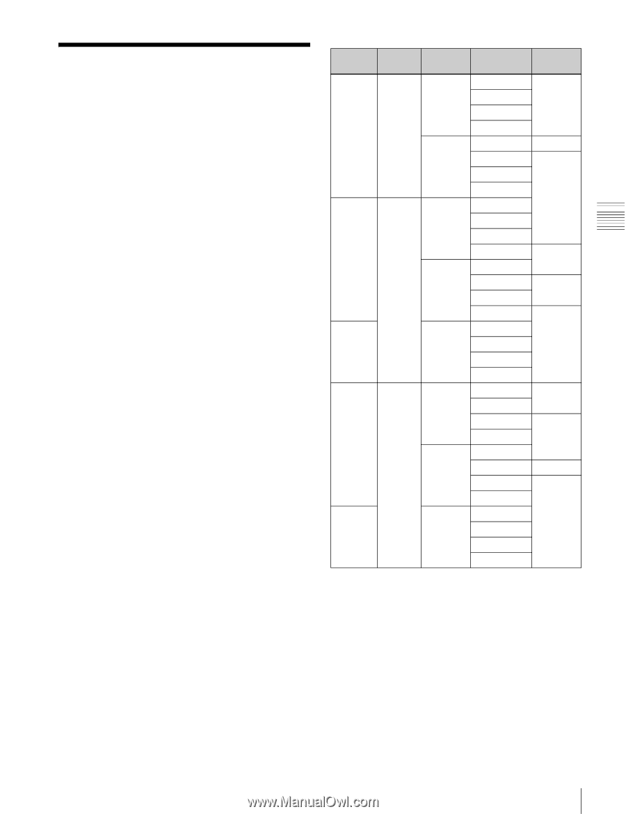
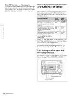
Chapter 3 Preparations 3-5 Setting Reference Video Signals This section explains how reference video signals for synchronization of video output and servo lock are selected according to settings made with this unit. Reference video signal for video output Output video signals are synchronized with the signal generated by the internal reference video signal generator. The internal reference video signal generator can be synchronized with an external reference video signal or with an input video signal (HD SDI input). Reference video signal for servo lock Servo is locked with an external reference video signal, an input video signal (HD SDI input), or the signal generated by the internal reference video signal generator. As shown in the following table, a signal for synchronization of the internal reference video signal generator and a reference video signal for servo lock are selected according to the setting for setup menu items 309 and 334, the setting for OUT REF on the P2 VIDEO page of the function menu, and the operating mode of the unit. For details on setup menu item 309, see page 68, and for item 334, see page 68. For details on the OUT REF settings, see "3-7 Basic Operations of the Function Menu" on page 31. OUT REF Item 309 Item 334 setting setting setting -- EXT NORMAL INPUT REF AUTO1 NORMAL INPUT INPUT -- REF AUTO2 NORMAL INPUT INPUT -- Operation mode EE PB ASSEMBLE REC EE PB ASSEMBLE REC EE PB ASSEMBLE REC EE PB ASSEMBLE REC EE PB ASSEMBLE REC EE PB ASSEMBLE REC EE PB ASSEMBLE REC EE PB ASSEMBLE REC Reference signal REF IPUT REF INPUT REF INPUT REF INPUT REF INPUT EE: E-E mode PB: Playback (Normal playback, jog mode, shuttle mode, stop mode) ASSEMBLE: Assemble edit mode (ASSEMBLE on the HOME page of the function menu is set to ON.) REC: Recording If the signal selected on the menu is not being input The servo reference video signal and internal reference signal generator synchronize as follows. When INPUT is selected for the sync signal If a video signal is not being input, the servo reference video signal and internal reference signal generator synchronize with an external reference video signal. 27 Setting Reference Video Signals
-
 1
1 -
2
-
3
-
4
-
5
-
6
-
7
-
8
-
9
-
10
-
11
-
12
-
13
-
14
-
15
-
16
-
17
-
18
-
19
-
20
-
21
-
 22
22 -
 23
23 -
 24
24 -
 25
25 -
 26
26 -
 27
27 -
 28
28 -
 29
29 -
 30
30 -
 31
31 -
 32
32 -
33
-
34
-
35
-
36
-
37
-
38
-
39
-
40
-
41
-
42
-
43
-
44
-
45
-
46
-
47
-
48
-
49
-
50
-
51
-
52
-
53
-
54
-
55
-
56
-
57
-
58
-
59
-
60
-
61
-
62
-
63
-
64
-
65
-
66
-
67
-
68
-
69
-
70
-
71
-
72
-
73
-
74
-
75
-
76
-
77
-
78
-
79
-
80
-
81
-
82
-
83
-
84
-
85
-
86
-
87
-
88
-
89
-
90
-
91
-
92
-
93
-
94
 |
 |