Sony HDWS280 Product Manual (Operation Manual 1st Edition (Revised 5)) - Page 20
Rear Panel
 |
View all Sony HDWS280 manuals
Add to My Manuals
Save this manual to your list of manuals |
Page 20 highlights
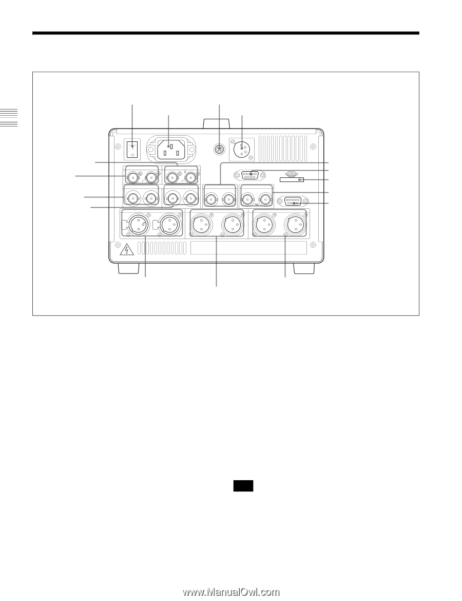
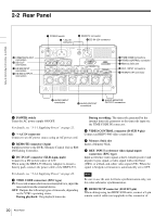
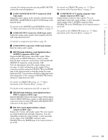
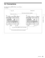
2-2 Rear Panel qh COMPOSITE OUT connectors qg SDI OUT connectors qf HD SDI INPUT connectors qd HD SDI OUTPUT connectors 1 POWER switch 2 -AC IN connector 3 REMOTE connector 4 DC IN 12V connector POWER ON - AC IN REMOTE DC IN 12V OFF SDI OUT 1 2 COMPOSITE OUT 1 VIDEO CONTROL (SUPER) (SUPER) INPUT HD SDI OUTPUT IN MONI 1 2 TIME CODE IN IOUT REF. INPUT REMOTE 9P (SUPER) AUDIO INPUT 1 2 AUDIO OUTPUT 1 2 AUDIO MONITOR OUTPUT R L 5 TIME CODE connectors 6 VIDEO CONTROL connector 7 Memory Stick slot 8 REF. INPUT connectors 9 REMOTE 9P connector Chapter 2 Names and Functions of Parts 2 2 2 2 1 1 3 3 3 3 3 PUSH PUSH 1 1 1 1 2 2 qs AUDIO INPUT connectors qa AUDIO OUTPUT connectors 0 AUDIO MONITOR OUTPUT connectors a POWER switch Turns the AC power supply ON/OFF. For details, see "3-1-1 Supplying Power" on page 22. b -AC IN connector Connect to an AC power source using an AC power cord. c REMOTE connector (4-pin) Supplies power to the BVR-3 Remote Control Unit or RM280 Editing Controller. d DC IN 12V connector (XLR 4-pin, male) Connect to a DC power source of 12V. When using the BKP-L551 Battery Adaptor to mount a battery pack, connect the power cable of the BKP-L551. For details, see "3-1-1 Supplying Power" on page 22. e TIME CODE connectors (BNC type) IN: To record a timecode from an external device, input the timecode from the external device. OUT: Outputs the following types of timecode, depending on the VTR's operating status. During playback: The playback timecode During recording: The timecode generated by the internal timecode generator or the timecode input via the TIME CODE IN connector. f VIDEO CONTROL connector (D-SUB 9-pin) Connect an HKDV-900 video control unit. g Memory Stick slot Insert a Memory Stick. h REF. INPUT (reference video signal input) connectors (BNC type) Input a reference video signal, a three-valued (positive and negative) sync signal, a video signal with color burst (VBS), or a black-and-white video signal (VS). When the signal is bridged, termination is automatically set to OFF. Note Be sure to use the unit for frame synchronization only, not for color subcarrier synchronization. i REMOTE 9P connector (D-SUB 9-pin) When editing using two HDW-S280 units, connect a 9-pin remote control cable (not supplied) to this connector of 20 Rear Panel
-
 1
1 -
2
-
3
-
4
-
5
-
6
-
7
-
8
-
9
-
10
-
11
-
12
-
13
-
14
-
 15
15 -
 16
16 -
 17
17 -
 18
18 -
 19
19 -
 20
20 -
 21
21 -
 22
22 -
 23
23 -
 24
24 -
 25
25 -
26
-
27
-
28
-
29
-
30
-
31
-
32
-
33
-
34
-
35
-
36
-
37
-
38
-
39
-
40
-
41
-
42
-
43
-
44
-
45
-
46
-
47
-
48
-
49
-
50
-
51
-
52
-
53
-
54
-
55
-
56
-
57
-
58
-
59
-
60
-
61
-
62
-
63
-
64
-
65
-
66
-
67
-
68
-
69
-
70
-
71
-
72
-
73
-
74
-
75
-
76
-
77
-
78
-
79
-
80
-
81
-
82
-
83
-
84
-
85
-
86
-
87
-
88
-
89
-
90
-
91
-
92
-
93
-
94
 |
 |