Sony HDWS280 Product Manual (Operation Manual 1st Edition (Revised 5)) - Page 14
Menu Operation
 |
View all Sony HDWS280 manuals
Add to My Manuals
Save this manual to your list of manuals |
Page 14 highlights
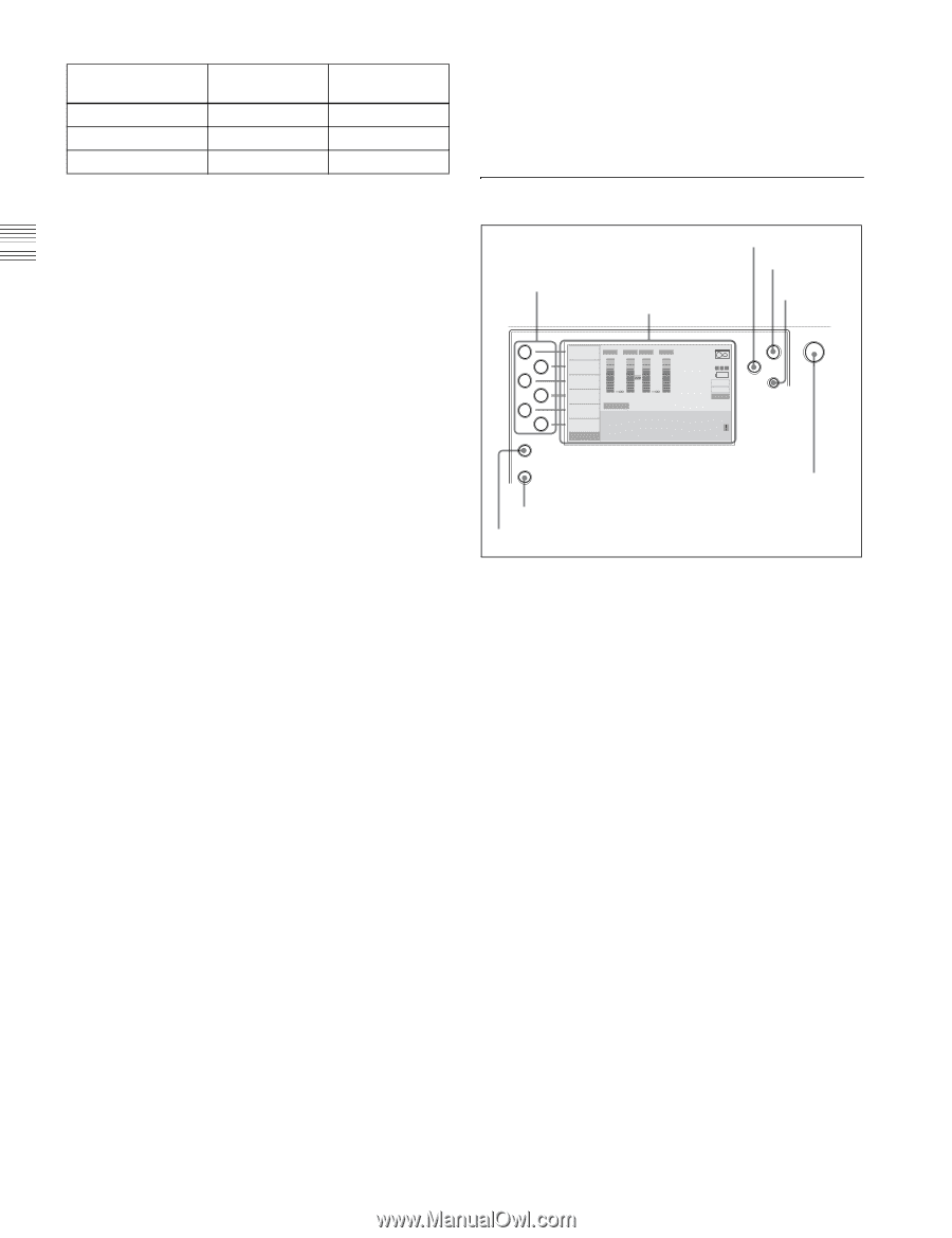
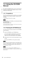
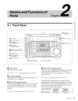
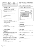
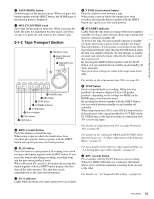
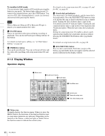
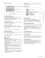
Chapter 2 Names and Functions of Parts Adjustment knob REC LEVEL 2 PB LEVEL 1 PB LEVEL 2 Recording channel Channel 2 Channel 3 Channel 4 Playback channel Channel 4 Channel 1 Channel 2 e R/P LEVEL CTL switch VAR: Enables adjustment with the PB LEVEL adjustment knobs or REC LEVEL adjustment knobs while you view the audio level meter in E-E mode. PRESET: Presets to fixed levels. Levels cannot be adjusted with the PB LEVEL adjustment knobs or REC LEVEL adjustment knobs. For Switching to E-E mode, see " To monitor in E-E mode" on page 16. f LEVEL adjustment knob Adjusts the volume of the headphones connected to the PHONES jack. g PHONES (headphones) jack Connect headphones. h REC INHI switch and indicator ON: Recording on the tape is inhibited, regardless of the state of the cassette's erasure prevention plug. The REC INHI indicator lights. OFF: Recording on the tape is enabled when the cassette's erasure prevention plug is set to the original position. i KEY INHI switch When this switch is set to ON, the functions of the buttons selected with setup menu item 118 are inhibited. For details on setup menu item 118, see page 66. j Cassette compartment Insert a cassette here. k EJECT button Press to eject the cassette. The cassette mark in the display window flashes while the cassette is being ejected. l REMOTE button Selects the operation mode of this unit. When the button is not lit, the unit is controlled from the front panel of this unit. Normally use this status. When the button has been pressed and is lit, this unit is controlled from the device connected to the REMOTE 9P connector. In this case, all VTR operations using this unit's front panel are disabled except those of the STOP and EJECT buttons. When two HDW-S280 units are connected, press this button on the player VTR to make it lit. You can determine which tape transport buttons on the front panel are to be enabled when the REMOTE button is lit with setup menu item 006. For details on setup menu item 006, see page 63. 2-1-1 Menu Operation Section 3 MENU button 1 Function buttons 2 Display window 4 DISPLAY button 5 RESET button SHIFT CHARACTR ON PB/EE PB CONFI ENABLE CTL/TC TC EMPH EMPH EMPH EMPH 0 0 -10 -10 -20 -20 -30 -30 -40 -40 1 23 4 HD INPUT : ANA CH1 IN : -60 CH2 IN : -4 COND OUT : +4 MONI L : 1 BANK 2 MONI R : 2 D-STOP DOLBY NR P ROLL ASSEMBLE 59.94i SDI ASMBL CONFI ON RECORDER OFF LTC DF VITC LTC EXT-LTC R-RUN REM:00M TCG SET HOME 00:00:00:00. DISPLAY MULTI CONTROL MENU RESET PUSH PITCH CTL PAGE HOME 7 PAGE/HOME button 6 SHIFT button 8 MULTI CONTROL knob a Function buttons Select and set menu items displayed in the display window. b Display window Displays menus, audio level meters, and data such as time data or meta-data. The DISPLAY button let you switch to the video monitor display. For details, see "2-1-3 Display Window" on page 16. c MENU button Displays a setup menu item in the time data display area of the display window. For details on the setup menu operations, see "9-2 Setup Menu Operations" on page 60. d DISPLAY button Switches the operation display to the video monitor display and vice versa. e RESET button Resets the CTL data displayed in the display window or the initial value of the timecode generator. f SHIFT button Switches between functions for any button with two functions. 14 Front Panel
-
 1
1 -
2
-
3
-
4
-
5
-
6
-
7
-
8
-
 9
9 -
 10
10 -
 11
11 -
 12
12 -
 13
13 -
 14
14 -
 15
15 -
 16
16 -
 17
17 -
 18
18 -
 19
19 -
20
-
21
-
22
-
23
-
24
-
25
-
26
-
27
-
28
-
29
-
30
-
31
-
32
-
33
-
34
-
35
-
36
-
37
-
38
-
39
-
40
-
41
-
42
-
43
-
44
-
45
-
46
-
47
-
48
-
49
-
50
-
51
-
52
-
53
-
54
-
55
-
56
-
57
-
58
-
59
-
60
-
61
-
62
-
63
-
64
-
65
-
66
-
67
-
68
-
69
-
70
-
71
-
72
-
73
-
74
-
75
-
76
-
77
-
78
-
79
-
80
-
81
-
82
-
83
-
84
-
85
-
86
-
87
-
88
-
89
-
90
-
91
-
92
-
93
-
94
 |
 |