TP-Link T2700G-28TQ T2700G-28TQ User Guide V1 - Page 104
GVRP, Configuration Procedure of VLAN VPN Function
 |
View all TP-Link T2700G-28TQ manuals
Add to My Manuals
Save this manual to your list of manuals |
Page 104 highlights
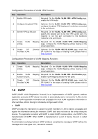
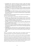
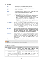
Configuration Procedure of VLAN VPN Function: Step Operation Description 1 Enable VPN mode. Required. On the VLAN→VLAN VPN→VPN Config page, enable the VPN mode. 2 Configure the global TPID. Optional. On the VLAN→VLAN VPN→VPN Config page, configure the global TPID basing on the devices connected to the up-link port. 3 Set the VPN up-link port. Required. On the VLAN→VLAN VPN→VPN Config page, specify the desired port to be the VPN up-link port. It's required to set the port connected to the backbone networks to be up-link port. 4 Create VLAN Mapping Required. On the VLAN→VLAN VPN→VLAN Mapping entries. page, configure the VLAN Mapping entries basing on the actual application. 5 Create SP (Service Optional. On the VLAN→802.1Q VLAN page, create the Provider) VLAN. SP VLAN. For the steps of creating VLAN, please refer to 802.1Q VLAN. Configuration Procedure of VLAN Mapping Function: Step Operation 1 Create VLAN entries. 2 Enable VLAN function for port. 3 Create SP Provider) VLAN Description Mapping Required. On the VLAN→VLAN VPN→VLAN Mapping page, configure the VLAN Mapping entries basing on the actual application. Mapping Required. On the VLAN→VLAN VPN→Port Enable page, enable VLAN Mapping function for the ports. (Service Optional. On the VLAN→802.1Q VLAN page, create the SP VLAN. For the steps of creating VLAN, please refer to 802.1Q VLAN. 7.8 GVRP GVRP (GARP VLAN Registration Protocol) is an implementation of GARP (generic attribute registration protocol). GVRP allows the switch to automatically add or remove the VLANs via the dynamic VLAN registration information and propagate the local VLAN registration information to other switches, without having to individually configure each VLAN. GARP GARP provides the mechanism to assist the switch members in LAN to deliver, propagate and register the information among the members. GARP itself does not work as the entity among the devices. The application complied with GARP is called GARP implementation, and GVRP is the implementation of GARP. When GARP is implemented on a port of device, the port is called GARP entity. The information exchange between GARP entities is completed by messages. GARP defines the messages into three types: Join, Leave and LeaveAll. 92
-
 1
1 -
2
-
3
-
4
-
5
-
6
-
7
-
8
-
9
-
10
-
11
-
12
-
13
-
14
-
15
-
16
-
17
-
18
-
19
-
20
-
21
-
22
-
23
-
24
-
25
-
26
-
27
-
28
-
29
-
30
-
31
-
32
-
33
-
34
-
35
-
36
-
37
-
38
-
39
-
40
-
41
-
42
-
43
-
44
-
45
-
46
-
47
-
48
-
49
-
50
-
51
-
52
-
53
-
54
-
55
-
56
-
57
-
58
-
59
-
60
-
61
-
62
-
63
-
64
-
65
-
66
-
67
-
68
-
69
-
70
-
71
-
72
-
73
-
74
-
75
-
76
-
77
-
78
-
79
-
80
-
81
-
82
-
83
-
84
-
85
-
86
-
87
-
88
-
89
-
90
-
91
-
92
-
93
-
94
-
95
-
96
-
97
-
98
-
 99
99 -
 100
100 -
 101
101 -
 102
102 -
 103
103 -
 104
104 -
 105
105 -
 106
106 -
 107
107 -
 108
108 -
 109
109 -
110
-
111
-
112
-
113
-
114
-
115
-
116
-
117
-
118
-
119
-
120
-
121
-
122
-
123
-
124
-
125
-
126
-
127
-
128
-
129
-
130
-
131
-
132
-
133
-
134
-
135
-
136
-
137
-
138
-
139
-
140
-
141
-
142
-
143
-
144
-
145
-
146
-
147
-
148
-
149
-
150
-
151
-
152
-
153
-
154
-
155
-
156
-
157
-
158
-
159
-
160
-
161
-
162
-
163
-
164
-
165
-
166
-
167
-
168
-
169
-
170
-
171
-
172
-
173
-
174
-
175
-
176
-
177
-
178
-
179
-
180
-
181
-
182
-
183
-
184
-
185
-
186
-
187
-
188
-
189
-
190
-
191
-
192
-
193
-
194
-
195
-
196
-
197
-
198
-
199
-
200
-
201
-
202
-
203
-
204
-
205
-
206
-
207
-
208
-
209
-
210
-
211
-
212
-
213
-
214
-
215
-
216
-
217
-
218
-
219
-
220
-
221
-
222
-
223
-
224
-
225
-
226
-
227
-
228
-
229
-
230
-
231
-
232
-
233
-
234
-
235
-
236
-
237
-
238
-
239
-
240
-
241
-
242
-
243
-
244
-
245
-
246
-
247
-
248
-
249
-
250
-
251
-
252
-
253
-
254
-
255
-
256
-
257
-
258
-
259
-
260
-
261
-
262
-
263
-
264
-
265
-
266
-
267
-
268
-
269
-
270
-
271
-
272
-
273
-
274
-
275
-
276
-
277
-
278
-
279
-
280
-
281
-
282
-
283
-
284
-
285
-
286
-
287
-
288
-
289
-
290
-
291
-
292
-
293
-
294
-
295
-
296
-
297
-
298
-
299
-
300
-
301
-
302
-
303
-
304
-
305
-
306
-
307
-
308
-
309
-
310
-
311
-
312
-
313
-
314
-
315
-
316
-
317
-
318
-
319
-
320
-
321
-
322
-
323
-
324
-
325
-
326
-
327
-
328
-
329
-
330
-
331
-
332
-
333
-
334
-
335
-
336
-
337
-
338
-
339
-
340
-
341
-
342
-
343
-
344
-
345
-
346
-
347
-
348
-
349
-
350
-
351
-
352
-
353
-
354
-
355
-
356
-
357
-
358
-
359
-
360
-
361
-
362
-
363
-
364
-
365
-
366
-
367
-
368
-
369
-
370
-
371
-
372
-
373
-
374
-
375
-
376
-
377
-
378
-
379
-
380
-
381
-
382
-
383
-
384
-
385
-
386
-
387
-
388
-
389
-
390
-
391
-
392
-
393
-
394
-
395
-
396
-
397
-
398
-
399
-
400
-
401
-
402
-
403
-
404
-
405
-
406
-
407
-
408
-
409
-
410
-
411
-
412
-
413
-
414
-
415
-
416
-
417
-
418
-
419
-
420
 |
 |
