TP-Link T2700G-28TQ T2700G-28TQ User Guide V1 - Page 226
Backup Group 1, corresponding to Virtual Router 1. Device A is the master router; Device
 |
View all TP-Link T2700G-28TQ manuals
Add to My Manuals
Save this manual to your list of manuals |
Page 226 highlights
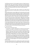
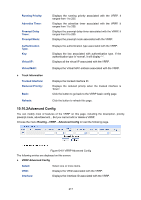
interfaces and better performance can be elected as master router; and the stability of backup group is increased. When the router interface connecting the uplink fails, the backup group cannot recognize uplink breakdown. If this router is in Master state, hosts in the LAN cannot visit external network. This problem can be solved with the help of interface tracking function. When the interface connecting the uplink is down, the router will automatically lower its priority, making priority of other routers in the backup group higher than its priority value. As a result, the backup router with the highest priority becomes master. Load Balancing One router can work in more than one backup group, which makes it possible that a router can be master router in one backup group and backup router in other backup groups. Load balancing means multiple routers undertake workloads simultaneously. Therefore, two or more backup groups are needed to realize load balancing. Each backup group consists of one master router and several backup routers. Master router can vary from one backup group to the others. Figure 10-58 VRRP Load Balancing A router owns different priority in different backup groups when it participates in multiple VRRP backup groups simultaneously. In Figure 10-58, there exist three backup groups: • Backup Group 1, corresponding to Virtual Router 1. Device A is the master router; Device B and C are backup routers. • Backup Group 2, corresponding to Virtual Router 2. Device B is the master router; Device A and C are backup routers. • Backup Group 3, corresponding to Virtual Router 3. Device C is the master router; Device A and B are backup routers. To realize the workload balancing among Device A, B and C, the default gateway of the hosts associated with the LAN should be set as Virtual Router 1, 2 and 3 respectively. When it comes to priority configuration, it would be better that the VRRP priority values of the three virtual routers are different in order to prevent one router from being more than one master simultaneously. 214
-
 1
1 -
2
-
3
-
4
-
5
-
6
-
7
-
8
-
9
-
10
-
11
-
12
-
13
-
14
-
15
-
16
-
17
-
18
-
19
-
20
-
21
-
22
-
23
-
24
-
25
-
26
-
27
-
28
-
29
-
30
-
31
-
32
-
33
-
34
-
35
-
36
-
37
-
38
-
39
-
40
-
41
-
42
-
43
-
44
-
45
-
46
-
47
-
48
-
49
-
50
-
51
-
52
-
53
-
54
-
55
-
56
-
57
-
58
-
59
-
60
-
61
-
62
-
63
-
64
-
65
-
66
-
67
-
68
-
69
-
70
-
71
-
72
-
73
-
74
-
75
-
76
-
77
-
78
-
79
-
80
-
81
-
82
-
83
-
84
-
85
-
86
-
87
-
88
-
89
-
90
-
91
-
92
-
93
-
94
-
95
-
96
-
97
-
98
-
99
-
100
-
101
-
102
-
103
-
104
-
105
-
106
-
107
-
108
-
109
-
110
-
111
-
112
-
113
-
114
-
115
-
116
-
117
-
118
-
119
-
120
-
121
-
122
-
123
-
124
-
125
-
126
-
127
-
128
-
129
-
130
-
131
-
132
-
133
-
134
-
135
-
136
-
137
-
138
-
139
-
140
-
141
-
142
-
143
-
144
-
145
-
146
-
147
-
148
-
149
-
150
-
151
-
152
-
153
-
154
-
155
-
156
-
157
-
158
-
159
-
160
-
161
-
162
-
163
-
164
-
165
-
166
-
167
-
168
-
169
-
170
-
171
-
172
-
173
-
174
-
175
-
176
-
177
-
178
-
179
-
180
-
181
-
182
-
183
-
184
-
185
-
186
-
187
-
188
-
189
-
190
-
191
-
192
-
193
-
194
-
195
-
196
-
197
-
198
-
199
-
200
-
201
-
202
-
203
-
204
-
205
-
206
-
207
-
208
-
209
-
210
-
211
-
212
-
213
-
214
-
215
-
216
-
217
-
218
-
219
-
220
-
 221
221 -
 222
222 -
 223
223 -
 224
224 -
 225
225 -
 226
226 -
 227
227 -
 228
228 -
 229
229 -
 230
230 -
 231
231 -
232
-
233
-
234
-
235
-
236
-
237
-
238
-
239
-
240
-
241
-
242
-
243
-
244
-
245
-
246
-
247
-
248
-
249
-
250
-
251
-
252
-
253
-
254
-
255
-
256
-
257
-
258
-
259
-
260
-
261
-
262
-
263
-
264
-
265
-
266
-
267
-
268
-
269
-
270
-
271
-
272
-
273
-
274
-
275
-
276
-
277
-
278
-
279
-
280
-
281
-
282
-
283
-
284
-
285
-
286
-
287
-
288
-
289
-
290
-
291
-
292
-
293
-
294
-
295
-
296
-
297
-
298
-
299
-
300
-
301
-
302
-
303
-
304
-
305
-
306
-
307
-
308
-
309
-
310
-
311
-
312
-
313
-
314
-
315
-
316
-
317
-
318
-
319
-
320
-
321
-
322
-
323
-
324
-
325
-
326
-
327
-
328
-
329
-
330
-
331
-
332
-
333
-
334
-
335
-
336
-
337
-
338
-
339
-
340
-
341
-
342
-
343
-
344
-
345
-
346
-
347
-
348
-
349
-
350
-
351
-
352
-
353
-
354
-
355
-
356
-
357
-
358
-
359
-
360
-
361
-
362
-
363
-
364
-
365
-
366
-
367
-
368
-
369
-
370
-
371
-
372
-
373
-
374
-
375
-
376
-
377
-
378
-
379
-
380
-
381
-
382
-
383
-
384
-
385
-
386
-
387
-
388
-
389
-
390
-
391
-
392
-
393
-
394
-
395
-
396
-
397
-
398
-
399
-
400
-
401
-
402
-
403
-
404
-
405
-
406
-
407
-
408
-
409
-
410
-
411
-
412
-
413
-
414
-
415
-
416
-
417
-
418
-
419
-
420
 |
 |
