TP-Link T2700G-28TQ T2700G-28TQ User Guide V1 - Page 160
DHCP Server, Configuration Procedure, Steps, Operation, Routing, Interface, Interface Config
 |
View all TP-Link T2700G-28TQ manuals
Add to My Manuals
Save this manual to your list of manuals |
Page 160 highlights
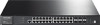
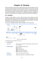
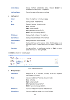
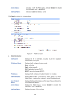
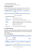
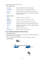
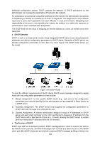
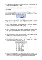
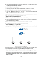
Configuration Procedure Configure Switch A Steps Operation Note 1 Add interface VLAN 10 Required. On page Routing→Interface→Interface Config, add interface VLAN 10 with the mode as static, the IP address as 192.168.0.1, the mask as 255.255.255.0 and the interface name as VLAN10. 2 Add interface VLAN 20 Required. On page Routing→Interface→Interface Config, add interface VLAN 20 with the mode as static, the IP address as 192.168.1.1, the mask as 255.255.255.0 and the interface name as VLAN20. 3 Add static route Required. On page Routing→Static Routing→Static Routing entry Config, add a static route entry with the destination as 192.168.2.0, the subnet mask as 255.255.255.0 and the next hop as 192.168.1.2. Configure Switch B Steps Operation 1 Add interface VLAN 20 2 Add interface VLAN 30 3 Add static route entry Note Required. On page Routing→Interface→Interface Config, add interface VLAN 20 with the mode as static, the IP address as 192.168.1.2, the mask as 255.255.255.0 and the interface name as VLAN20. Required. On page Routing→Interface→Interface Config, add interface VLAN 30 with the mode as static, the IP address as 192.168.2.1, the mask as 255.255.255.0 and the interface name as VLAN30. Required. On page Routing→Static Routing→Static Routing Config, add a static route entry with the destination as 192.168.0.0, the subnet mask as 255.255.255.0 and the next hop as 192.168.1.1. Configure the PCs Configure the default gateway of PC1 as 192.168.0.1 and the default gateway of PC2 as 192.168.2.1. 10.4 DHCP Server DHCP module is used to configure the DHCP functions of the switch, including two submenus, DHCP Server and DHCP Relay. Overview DHCP (Dynamic Host Configuration Protocol) is a network configuration protocol for hosts on TCP/IP networks, and it provides a framework for distributing configuration information to hosts. DHCP is adding the capability of automatic allocation of reusable network addresses and 148
-
 1
1 -
2
-
3
-
4
-
5
-
6
-
7
-
8
-
9
-
10
-
11
-
12
-
13
-
14
-
15
-
16
-
17
-
18
-
19
-
20
-
21
-
22
-
23
-
24
-
25
-
26
-
27
-
28
-
29
-
30
-
31
-
32
-
33
-
34
-
35
-
36
-
37
-
38
-
39
-
40
-
41
-
42
-
43
-
44
-
45
-
46
-
47
-
48
-
49
-
50
-
51
-
52
-
53
-
54
-
55
-
56
-
57
-
58
-
59
-
60
-
61
-
62
-
63
-
64
-
65
-
66
-
67
-
68
-
69
-
70
-
71
-
72
-
73
-
74
-
75
-
76
-
77
-
78
-
79
-
80
-
81
-
82
-
83
-
84
-
85
-
86
-
87
-
88
-
89
-
90
-
91
-
92
-
93
-
94
-
95
-
96
-
97
-
98
-
99
-
100
-
101
-
102
-
103
-
104
-
105
-
106
-
107
-
108
-
109
-
110
-
111
-
112
-
113
-
114
-
115
-
116
-
117
-
118
-
119
-
120
-
121
-
122
-
123
-
124
-
125
-
126
-
127
-
128
-
129
-
130
-
131
-
132
-
133
-
134
-
135
-
136
-
137
-
138
-
139
-
140
-
141
-
142
-
143
-
144
-
145
-
146
-
147
-
148
-
149
-
150
-
151
-
152
-
153
-
154
-
 155
155 -
 156
156 -
 157
157 -
 158
158 -
 159
159 -
 160
160 -
 161
161 -
 162
162 -
 163
163 -
 164
164 -
 165
165 -
166
-
167
-
168
-
169
-
170
-
171
-
172
-
173
-
174
-
175
-
176
-
177
-
178
-
179
-
180
-
181
-
182
-
183
-
184
-
185
-
186
-
187
-
188
-
189
-
190
-
191
-
192
-
193
-
194
-
195
-
196
-
197
-
198
-
199
-
200
-
201
-
202
-
203
-
204
-
205
-
206
-
207
-
208
-
209
-
210
-
211
-
212
-
213
-
214
-
215
-
216
-
217
-
218
-
219
-
220
-
221
-
222
-
223
-
224
-
225
-
226
-
227
-
228
-
229
-
230
-
231
-
232
-
233
-
234
-
235
-
236
-
237
-
238
-
239
-
240
-
241
-
242
-
243
-
244
-
245
-
246
-
247
-
248
-
249
-
250
-
251
-
252
-
253
-
254
-
255
-
256
-
257
-
258
-
259
-
260
-
261
-
262
-
263
-
264
-
265
-
266
-
267
-
268
-
269
-
270
-
271
-
272
-
273
-
274
-
275
-
276
-
277
-
278
-
279
-
280
-
281
-
282
-
283
-
284
-
285
-
286
-
287
-
288
-
289
-
290
-
291
-
292
-
293
-
294
-
295
-
296
-
297
-
298
-
299
-
300
-
301
-
302
-
303
-
304
-
305
-
306
-
307
-
308
-
309
-
310
-
311
-
312
-
313
-
314
-
315
-
316
-
317
-
318
-
319
-
320
-
321
-
322
-
323
-
324
-
325
-
326
-
327
-
328
-
329
-
330
-
331
-
332
-
333
-
334
-
335
-
336
-
337
-
338
-
339
-
340
-
341
-
342
-
343
-
344
-
345
-
346
-
347
-
348
-
349
-
350
-
351
-
352
-
353
-
354
-
355
-
356
-
357
-
358
-
359
-
360
-
361
-
362
-
363
-
364
-
365
-
366
-
367
-
368
-
369
-
370
-
371
-
372
-
373
-
374
-
375
-
376
-
377
-
378
-
379
-
380
-
381
-
382
-
383
-
384
-
385
-
386
-
387
-
388
-
389
-
390
-
391
-
392
-
393
-
394
-
395
-
396
-
397
-
398
-
399
-
400
-
401
-
402
-
403
-
404
-
405
-
406
-
407
-
408
-
409
-
410
-
411
-
412
-
413
-
414
-
415
-
416
-
417
-
418
-
419
-
420
 |
 |
