Toshiba Tecra A3-S711 User Manual - Page 57
Underside, Battery, Battery Pack Lock, Latch, Docking Port
 |
View all Toshiba Tecra A3-S711 manuals
Add to My Manuals
Save this manual to your list of manuals |
Page 57 highlights
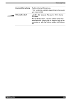
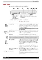
The Grand Tour Underside The following figure shows the underside of the computer. Make sure the display is closed before turning over your computer. 7 5 6 3 4 2 1 9 2 1 1. BATTERY PACK 2. BATTERY PACK LOCK 3. BATTERY PACK RELEASE LATCH 4. DOCKING PORT 8 5. EXPANSION MEMORY SOCKET 6. SLIM SELECT BAY LATCH * 7. SLIM SELECT BAY LOCK * 8. DOCKING HOLE 9. FAN VENT * available depending on the model you purchased. The underside of the computer Battery Pack This is the battery pack, which powers the computer when the AC adaptor is not connected. For detailed information on the battery pack, refer to Chapter 6, Power System. Battery Pack Lock There are two battery latches that secure the battery pack. To remove the battery pack, first slide the battery pack lock. Battery Pack Release Second, hold and slide the battery pack release Latch latch to left to remove the battery pack. Docking Port Use this port to connect an optional Port Replicator. Keep foreign objects out of the docking port. A pin or similar object can damage the computer's circuitry. TECRA A3/S2 2-8
-
 1
1 -
2
-
3
-
4
-
5
-
6
-
7
-
8
-
9
-
10
-
11
-
12
-
13
-
14
-
15
-
16
-
17
-
18
-
19
-
20
-
21
-
22
-
23
-
24
-
25
-
26
-
27
-
28
-
29
-
30
-
31
-
32
-
33
-
34
-
35
-
36
-
37
-
38
-
39
-
40
-
41
-
42
-
43
-
44
-
45
-
46
-
47
-
48
-
49
-
50
-
51
-
 52
52 -
 53
53 -
 54
54 -
 55
55 -
 56
56 -
 57
57 -
 58
58 -
 59
59 -
 60
60 -
 61
61 -
 62
62 -
63
-
64
-
65
-
66
-
67
-
68
-
69
-
70
-
71
-
72
-
73
-
74
-
75
-
76
-
77
-
78
-
79
-
80
-
81
-
82
-
83
-
84
-
85
-
86
-
87
-
88
-
89
-
90
-
91
-
92
-
93
-
94
-
95
-
96
-
97
-
98
-
99
-
100
-
101
-
102
-
103
-
104
-
105
-
106
-
107
-
108
-
109
-
110
-
111
-
112
-
113
-
114
-
115
-
116
-
117
-
118
-
119
-
120
-
121
-
122
-
123
-
124
-
125
-
126
-
127
-
128
-
129
-
130
-
131
-
132
-
133
-
134
-
135
-
136
-
137
-
138
-
139
-
140
-
141
-
142
-
143
-
144
-
145
-
146
-
147
-
148
-
149
-
150
-
151
-
152
-
153
-
154
-
155
-
156
-
157
-
158
-
159
-
160
-
161
-
162
-
163
-
164
-
165
-
166
-
167
-
168
-
169
-
170
-
171
-
172
-
173
-
174
-
175
-
176
-
177
-
178
-
179
-
180
-
181
-
182
 |
 |
