ZyXEL GS1500-24P User Guide - Page 117
Table 38
 |
View all ZyXEL GS1500-24P manuals
Add to My Manuals
Save this manual to your list of manuals |
Page 117 highlights
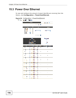
Chapter 15 Power Over Ethernet The following table describes the related labels in this screen. Table 38 Configuration > PowerOverEthernet LABEL DESCRIPTION PoE Mode Select the power management mode you want the Switch to use. Apply Port PD • classification - Select this if you want the Switch to reserve the Max Power (mW) to each PD according to the priority level. If the total power supply runs out, PDs with lower priority do not get power to function. • consumption - Select this if you want the Switch to manage the total power supply so that each connected PD gets a resource. However, the power allocated by the Switch may be less than the Max Power (mW) of the PD. PDs with higher priority also get more power than those with lower priority levels. Click Apply to save any changes made to the PoE mode to the Switch. Select the ports you want to change the PD and Priority values for. Select On to provide power to a PD connected to the port. Priority If turned Off, the PD connected to the port cannot receive power from the Switch. When the total power requested by the PDs exceeds the total PoE power budget on the Switch, you can set the PD priority to allow the Switch to provide power to ports with higher priority. Select Critical to give the highest PD priority on the port. Select High to set the Switch to assign the remaining power to the port after all critical priority ports are served. Apply Mode Total Power Consuming Power Allocated Power Select Low to set the Switch to assign the remaining power to the port after all critical and high priority ports are served. Click Apply to save any changes to the Switch. This field displays the power management mode used by the Switch, Classification or Consumption mode. This field displays the total power the Switch can provide to the connected PoE-enabled devices on the PoE ports. This field displays the amount of power the Switch is currently supplying to the connected PoE-enabled devices. This field displays the total amount of power the Switch has reserved for PoE after negotiating with the connected PoE device(s). Remaining Power Port PD Consuming Power can be less than or equal but not more than the Allocated Power. This field displays the amount of power the Switch can still provide for PoE. Note: The Switch must have at least 16 W of remaining power in order to supply power to a PoE device, even if the PoE device needs less than 16W. This is the port index number. This field shows which ports can receive power from the Switch. • Off - The PD connected to this port cannot get power supply. • On - The PD connected to this port can receive power. GS1500-24P User's Guide 117
-
 1
1 -
2
-
3
-
4
-
5
-
6
-
7
-
8
-
9
-
10
-
11
-
12
-
13
-
14
-
15
-
16
-
17
-
18
-
19
-
20
-
21
-
22
-
23
-
24
-
25
-
26
-
27
-
28
-
29
-
30
-
31
-
32
-
33
-
34
-
35
-
36
-
37
-
38
-
39
-
40
-
41
-
42
-
43
-
44
-
45
-
46
-
47
-
48
-
49
-
50
-
51
-
52
-
53
-
54
-
55
-
56
-
57
-
58
-
59
-
60
-
61
-
62
-
63
-
64
-
65
-
66
-
67
-
68
-
69
-
70
-
71
-
72
-
73
-
74
-
75
-
76
-
77
-
78
-
79
-
80
-
81
-
82
-
83
-
84
-
85
-
86
-
87
-
88
-
89
-
90
-
91
-
92
-
93
-
94
-
95
-
96
-
97
-
98
-
99
-
100
-
101
-
102
-
103
-
104
-
105
-
106
-
107
-
108
-
109
-
110
-
111
-
 112
112 -
 113
113 -
 114
114 -
 115
115 -
 116
116 -
 117
117 -
 118
118 -
 119
119 -
 120
120 -
 121
121 -
 122
122 -
123
-
124
-
125
-
126
-
127
-
128
-
129
-
130
-
131
-
132
-
133
-
134
-
135
-
136
-
137
-
138
-
139
-
140
-
141
-
142
-
143
-
144
-
145
-
146
-
147
-
148
-
149
-
150
-
151
-
152
-
153
-
154
-
155
-
156
-
157
-
158
-
159
-
160
-
161
-
162
-
163
-
164
-
165
-
166
-
167
-
168
-
169
-
170
-
171
-
172
-
173
-
174
-
175
-
176
-
177
-
178
-
179
-
180
-
181
-
182
-
183
-
184
-
185
-
186
-
187
-
188
-
189
-
190
-
191
-
192
-
193
-
194
-
195
-
196
-
197
-
198
-
199
-
200
-
201
-
202
-
203
-
204
-
205
-
206
-
207
-
208
-
209
-
210
-
211
-
212
-
213
-
214
-
215
-
216
-
217
-
218
 |
 |