ZyXEL GS1500-24P User Guide - Page 144
Table 49
 |
View all ZyXEL GS1500-24P manuals
Add to My Manuals
Save this manual to your list of manuals |
Page 144 highlights
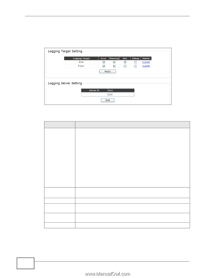
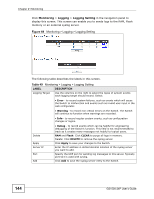
Chapter 21 Monitoring Click Monitoring > Logging > Logging Setting in the navigation panel to display this screen. This screen can enable you to sends logs to the RAM, Flash memory or an external syslog server. Figure 69 Monitoring > Logging > Logging Setting The following table describes the labels in this screen. Table 49 Monitoring > Logging > Logging Setting LABEL DESCRIPTION Logging Target Use the columns on the right to select the types of system events each logging target should record. Select: • Error - to record system failures, such as events which will cause the Switch to malfunction and events such as invalid user input in the web configurator. • Warning - to record non critical errors on the Switch. The Switch will continue to function when warnings are recorded. • Info - to record regular system events, such as configuration changes or logins. Delete Apply Server IP Port Add • Debug - to record events which can be helpful for engineering debugging of the Switch's function. This field is not recommended to track as it creates many messages not helpful to typical users. RAM and Flash: Click CLEAR to purge all logs in memory. Delete: Click DELETE to remove the syslog server. Click Apply to save your changes to the Switch. Enter the IP address in dotted decimal notation of the syslog server you want to add. Specify the UDP port for sending log messages to this server. Typically port 514 is used with syslog. Click Add to save the syslog server entry to the Switch. 144 GS1500-24P User's Guide
-
 1
1 -
2
-
3
-
4
-
5
-
6
-
7
-
8
-
9
-
10
-
11
-
12
-
13
-
14
-
15
-
16
-
17
-
18
-
19
-
20
-
21
-
22
-
23
-
24
-
25
-
26
-
27
-
28
-
29
-
30
-
31
-
32
-
33
-
34
-
35
-
36
-
37
-
38
-
39
-
40
-
41
-
42
-
43
-
44
-
45
-
46
-
47
-
48
-
49
-
50
-
51
-
52
-
53
-
54
-
55
-
56
-
57
-
58
-
59
-
60
-
61
-
62
-
63
-
64
-
65
-
66
-
67
-
68
-
69
-
70
-
71
-
72
-
73
-
74
-
75
-
76
-
77
-
78
-
79
-
80
-
81
-
82
-
83
-
84
-
85
-
86
-
87
-
88
-
89
-
90
-
91
-
92
-
93
-
94
-
95
-
96
-
97
-
98
-
99
-
100
-
101
-
102
-
103
-
104
-
105
-
106
-
107
-
108
-
109
-
110
-
111
-
112
-
113
-
114
-
115
-
116
-
117
-
118
-
119
-
120
-
121
-
122
-
123
-
124
-
125
-
126
-
127
-
128
-
129
-
130
-
131
-
132
-
133
-
134
-
135
-
136
-
137
-
138
-
 139
139 -
 140
140 -
 141
141 -
 142
142 -
 143
143 -
 144
144 -
 145
145 -
 146
146 -
 147
147 -
 148
148 -
 149
149 -
150
-
151
-
152
-
153
-
154
-
155
-
156
-
157
-
158
-
159
-
160
-
161
-
162
-
163
-
164
-
165
-
166
-
167
-
168
-
169
-
170
-
171
-
172
-
173
-
174
-
175
-
176
-
177
-
178
-
179
-
180
-
181
-
182
-
183
-
184
-
185
-
186
-
187
-
188
-
189
-
190
-
191
-
192
-
193
-
194
-
195
-
196
-
197
-
198
-
199
-
200
-
201
-
202
-
203
-
204
-
205
-
206
-
207
-
208
-
209
-
210
-
211
-
212
-
213
-
214
-
215
-
216
-
217
-
218
 |
 |