ZyXEL GS1500-24P User Guide - Page 28
Rack-mounted Installation Requirements, Attaching the Mounting Brackets to the Switch
 |
View all ZyXEL GS1500-24P manuals
Add to My Manuals
Save this manual to your list of manuals |
Page 28 highlights
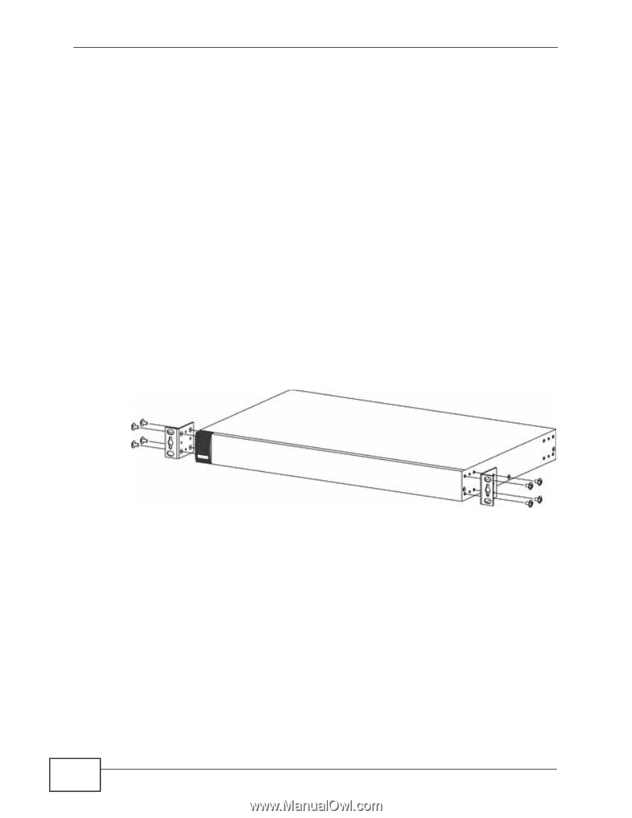
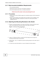
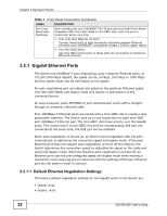
Chapter 2 Hardware Installation and Connection 2.3.1 Rack-mounted Installation Requirements • Two mounting brackets. • Eight M3 flat head screws and a #2 Philips screwdriver. • Four M5 flat head screws and a #2 Philips screwdriver. Failure to use the proper screws may damage the unit. 2.3.1.1 Precautions • Make sure the rack will safely support the combined weight of all the equipment it contains. • Make sure the position of the Switch does not make the rack unstable or topheavy. Take all necessary precautions to anchor the rack securely before installing the unit. 2.3.2 Attaching the Mounting Brackets to the Switch 1 Position a mounting bracket on one side of the Switch, lining up the four screw holes on the bracket with the screw holes on the side of the Switch. Figure 5 Attaching the Mounting Brackets 2 Using a #2 Philips screwdriver, install the M3 flat head screws through the mounting bracket holes into the Switch. 3 Repeat steps 1 and 2 to install the second mounting bracket on the other side of the Switch. 4 You may now mount the Switch on a rack. Proceed to the next section. 28 GS1500-24P User's Guide
-
 1
1 -
2
-
3
-
4
-
5
-
6
-
7
-
8
-
9
-
10
-
11
-
12
-
13
-
14
-
15
-
16
-
17
-
18
-
19
-
20
-
21
-
22
-
 23
23 -
 24
24 -
 25
25 -
 26
26 -
 27
27 -
 28
28 -
 29
29 -
 30
30 -
 31
31 -
 32
32 -
 33
33 -
34
-
35
-
36
-
37
-
38
-
39
-
40
-
41
-
42
-
43
-
44
-
45
-
46
-
47
-
48
-
49
-
50
-
51
-
52
-
53
-
54
-
55
-
56
-
57
-
58
-
59
-
60
-
61
-
62
-
63
-
64
-
65
-
66
-
67
-
68
-
69
-
70
-
71
-
72
-
73
-
74
-
75
-
76
-
77
-
78
-
79
-
80
-
81
-
82
-
83
-
84
-
85
-
86
-
87
-
88
-
89
-
90
-
91
-
92
-
93
-
94
-
95
-
96
-
97
-
98
-
99
-
100
-
101
-
102
-
103
-
104
-
105
-
106
-
107
-
108
-
109
-
110
-
111
-
112
-
113
-
114
-
115
-
116
-
117
-
118
-
119
-
120
-
121
-
122
-
123
-
124
-
125
-
126
-
127
-
128
-
129
-
130
-
131
-
132
-
133
-
134
-
135
-
136
-
137
-
138
-
139
-
140
-
141
-
142
-
143
-
144
-
145
-
146
-
147
-
148
-
149
-
150
-
151
-
152
-
153
-
154
-
155
-
156
-
157
-
158
-
159
-
160
-
161
-
162
-
163
-
164
-
165
-
166
-
167
-
168
-
169
-
170
-
171
-
172
-
173
-
174
-
175
-
176
-
177
-
178
-
179
-
180
-
181
-
182
-
183
-
184
-
185
-
186
-
187
-
188
-
189
-
190
-
191
-
192
-
193
-
194
-
195
-
196
-
197
-
198
-
199
-
200
-
201
-
202
-
203
-
204
-
205
-
206
-
207
-
208
-
209
-
210
-
211
-
212
-
213
-
214
-
215
-
216
-
217
-
218
 |
 |