ZyXEL P-314Plus User Guide - Page 207
PPTP is very similar to L2TP, since L2TP is based on both PPTP and L2F Cisco's Layer 2 Forwarding.
 |
View all ZyXEL P-314Plus manuals
Add to My Manuals
Save this manual to your list of manuals |
Page 207 highlights
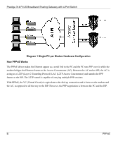
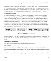
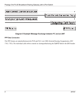
Prestige 314 PLUS Broadband Sharing Gateway with 4-Port Switch pass the PPTP packets to the internal PPTP server (i.e. NT server) behind the NAT. Users need to forward PPTP packets to port 1723 by configuring the server in Menu 15.2 - Server Set Setup. In the case above as the PPTP connection is initialized by the remote PPTP Client, the user must configure the PPTP clients. The Prestige initializes the PPTP connection hence, there is no need to configure the remote PPTP clients. PPTP Protocol Overview PPTP is very similar to L2TP, since L2TP is based on both PPTP and L2F (Cisco's Layer 2 Forwarding). Conceptually, there are three parties in PPTP, namely the PNS (PPTP Network Server), the PAC (PPTP Access Concentrator) and the PPTP user. The PNS is the box that hosts both the PPP and the PPTP stacks and forms one end of the PPTP tunnel. The PAC is the box that dials/answers the phone calls and relays the PPP frames to the PNS. The PPTP user is not necessarily a PPP client (can be a PPP server too). Both the PNS and the PAC must have IP connectivity; however, the PAC must in addition have dial-up capability. The phone call is between the user and the PAC and the PAC tunnels the PPP frames to the PNS. The PPTP user is unaware of the tunnel between the PAC and the PNS. Diagram 4 PPTP Protocol Overview Microsoft includes PPTP as a part of the Windows OS. In Microsoft's implementation, the PC, and hence the Prestige, is the PNS that requests the PAC (the ANT) to place an outgoing call over AAL5 to an RFC 2364 server. Control & PPP connections Each PPTP session has distinct control connection and PPP data connection. Call Connection The control connection runs over TCP. Similar to L2TP, a tunnel control connection is first established before call control messages can be exchanged. Please note that a tunnel control connection supports multiple call sessions. The following diagram depicts the message exchange of a successful call setup between a PC and an ANT. PPTP E
-
 1
1 -
2
-
3
-
4
-
5
-
6
-
7
-
8
-
9
-
10
-
11
-
12
-
13
-
14
-
15
-
16
-
17
-
18
-
19
-
20
-
21
-
22
-
23
-
24
-
25
-
26
-
27
-
28
-
29
-
30
-
31
-
32
-
33
-
34
-
35
-
36
-
37
-
38
-
39
-
40
-
41
-
42
-
43
-
44
-
45
-
46
-
47
-
48
-
49
-
50
-
51
-
52
-
53
-
54
-
55
-
56
-
57
-
58
-
59
-
60
-
61
-
62
-
63
-
64
-
65
-
66
-
67
-
68
-
69
-
70
-
71
-
72
-
73
-
74
-
75
-
76
-
77
-
78
-
79
-
80
-
81
-
82
-
83
-
84
-
85
-
86
-
87
-
88
-
89
-
90
-
91
-
92
-
93
-
94
-
95
-
96
-
97
-
98
-
99
-
100
-
101
-
102
-
103
-
104
-
105
-
106
-
107
-
108
-
109
-
110
-
111
-
112
-
113
-
114
-
115
-
116
-
117
-
118
-
119
-
120
-
121
-
122
-
123
-
124
-
125
-
126
-
127
-
128
-
129
-
130
-
131
-
132
-
133
-
134
-
135
-
136
-
137
-
138
-
139
-
140
-
141
-
142
-
143
-
144
-
145
-
146
-
147
-
148
-
149
-
150
-
151
-
152
-
153
-
154
-
155
-
156
-
157
-
158
-
159
-
160
-
161
-
162
-
163
-
164
-
165
-
166
-
167
-
168
-
169
-
170
-
171
-
172
-
173
-
174
-
175
-
176
-
177
-
178
-
179
-
180
-
181
-
182
-
183
-
184
-
185
-
186
-
187
-
188
-
189
-
190
-
191
-
192
-
193
-
194
-
195
-
196
-
197
-
198
-
199
-
200
-
201
-
 202
202 -
 203
203 -
 204
204 -
 205
205 -
 206
206 -
 207
207 -
 208
208 -
 209
209 -
 210
210 -
 211
211 -
 212
212 -
213
-
214
-
215
-
216
-
217
-
218
-
219
-
220
-
221
-
222
-
223
-
224
-
225
 |
 |
