Cisco AIR-AP1242AG-E-K9 Hardware Installation Guide - Page 33
Connecting the 5-GHz External Antennas
 |
View all Cisco AIR-AP1242AG-E-K9 manuals
Add to My Manuals
Save this manual to your list of manuals |
Page 33 highlights
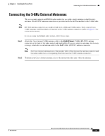
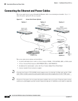
Chapter 2 Installing the Access Point Connecting the 5-GHz External Antennas Connecting the 5-GHz External Antennas The access point supports an RM22A radio module for use with a single antenna or dual diversity antennas. Two RP-TNC antenna connectors are provided on the back of the module for the 5-GHz radio. Note RP-TNC antenna connectors are used for both the 2.4-GHz and 5-GHz radios. Only connect Cisco 5-GHz antennas with blue labels or blue dots to the 5-GHz antenna connectors (refer to Figure 2-3 for connector locations). If you are using the RM22A radio module, follow these steps: Step 1 Attach the Cisco Aironet 5-GHz antenna cable to the Right/Primary 5-GHz (RP-TNC) antenna connector on the back of the radio module and hand tighten. If you are using two antennas for diversity coverage, attach the second antenna cable to the Left 5-GHz (RP-TNC) antenna connector. Note The Cisco Aironet antennas have a blue marker label or blue dot near the antenna connector and the radio module has a corresponding blue label near the 5-GHz antenna connectors. Step 2 To mount your Cisco Aironet antenna, refer to the instructions that came with your antenna. OL-4310-05 Cisco Aironet 1200 Series Access Point Hardware Installation Guide 2-7
-
 1
1 -
2
-
3
-
4
-
5
-
6
-
7
-
8
-
9
-
10
-
11
-
12
-
13
-
14
-
15
-
16
-
17
-
18
-
19
-
20
-
21
-
22
-
23
-
24
-
25
-
26
-
27
-
 28
28 -
 29
29 -
 30
30 -
 31
31 -
 32
32 -
 33
33 -
 34
34 -
 35
35 -
 36
36 -
 37
37 -
 38
38 -
39
-
40
-
41
-
42
-
43
-
44
-
45
-
46
-
47
-
48
-
49
-
50
-
51
-
52
-
53
-
54
-
55
-
56
-
57
-
58
-
59
-
60
-
61
-
62
-
63
-
64
-
65
-
66
-
67
-
68
-
69
-
70
-
71
-
72
-
73
-
74
-
75
-
76
-
77
-
78
-
79
-
80
-
81
-
82
-
83
-
84
-
85
-
86
-
87
-
88
-
89
-
90
-
91
-
92
-
93
-
94
-
95
-
96
-
97
-
98
-
99
-
100
-
101
-
102
-
103
-
104
-
105
-
106
-
107
-
108
-
109
-
110
-
111
-
112
-
113
-
114
-
115
-
116
-
117
-
118
-
119
-
120
-
121
-
122
-
123
-
124
-
125
-
126
-
127
-
128
-
129
-
130
-
131
-
132
-
133
-
134
-
135
-
136
-
137
-
138
-
139
-
140
-
141
-
142
-
143
-
144
-
145
-
146
-
147
-
148
-
149
-
150
-
151
-
152
-
153
-
154
-
155
-
156
-
157
-
158
-
159
-
160
 |
 |