Cisco AIR-AP1242AG-E-K9 Hardware Installation Guide - Page 82
Step 5, Caution, Cisco Aironet 1200 Series Access Point Hardware Installation Guide, OL-4310-05
 |
View all Cisco AIR-AP1242AG-E-K9 manuals
Add to My Manuals
Save this manual to your list of manuals |
Page 82 highlights
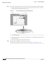
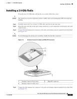
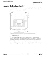
Installing a 2.4-GHz Radio Chapter 7 2.4-GHz Radio Upgrade Step 5 Insert the radio card into the access point's mini-PCI connector by following these steps: a. Tilt the radio card at approximately 20o to 30o so that its gold pins are aligned with the mini-PCI connector (see Figure 7-4). Step 6 Step 7 b. Push the card into the mini-PCI connector until it clicks into place. Carefully push the card down (towards the access point's motherboard) until the card-retaining clips lock into the notches on the side of the radio card (you will hear a click). Carefully position the antenna wires so that the metal connectors do not touch each other. Caution Do not allow antenna connectors to touch while power is applied, or the radio can be damaged. If they are touching, carefully rotate them in opposite directions until they are separated. Step 8 Step 9 Reinstall the 2.4-GHz radio access cover and use the T-10 tamper-resistant Torx L-wrench to tighten the cover's retaining screw. Look at the compliance labels on your access point. Depending on the model you originally ordered, there may be up to three labels affixed to the case. Cisco Aironet 1200 Series Access Point Hardware Installation Guide 7-8 OL-4310-05
-
 1
1 -
2
-
3
-
4
-
5
-
6
-
7
-
8
-
9
-
10
-
11
-
12
-
13
-
14
-
15
-
16
-
17
-
18
-
19
-
20
-
21
-
22
-
23
-
24
-
25
-
26
-
27
-
28
-
29
-
30
-
31
-
32
-
33
-
34
-
35
-
36
-
37
-
38
-
39
-
40
-
41
-
42
-
43
-
44
-
45
-
46
-
47
-
48
-
49
-
50
-
51
-
52
-
53
-
54
-
55
-
56
-
57
-
58
-
59
-
60
-
61
-
62
-
63
-
64
-
65
-
66
-
67
-
68
-
69
-
70
-
71
-
72
-
73
-
74
-
75
-
76
-
 77
77 -
 78
78 -
 79
79 -
 80
80 -
 81
81 -
 82
82 -
 83
83 -
 84
84 -
 85
85 -
 86
86 -
 87
87 -
88
-
89
-
90
-
91
-
92
-
93
-
94
-
95
-
96
-
97
-
98
-
99
-
100
-
101
-
102
-
103
-
104
-
105
-
106
-
107
-
108
-
109
-
110
-
111
-
112
-
113
-
114
-
115
-
116
-
117
-
118
-
119
-
120
-
121
-
122
-
123
-
124
-
125
-
126
-
127
-
128
-
129
-
130
-
131
-
132
-
133
-
134
-
135
-
136
-
137
-
138
-
139
-
140
-
141
-
142
-
143
-
144
-
145
-
146
-
147
-
148
-
149
-
150
-
151
-
152
-
153
-
154
-
155
-
156
-
157
-
158
-
159
-
160
 |
 |