Compaq ProLiant 1000 User Guide: Online Storage Controller Recovery Option - Page 45
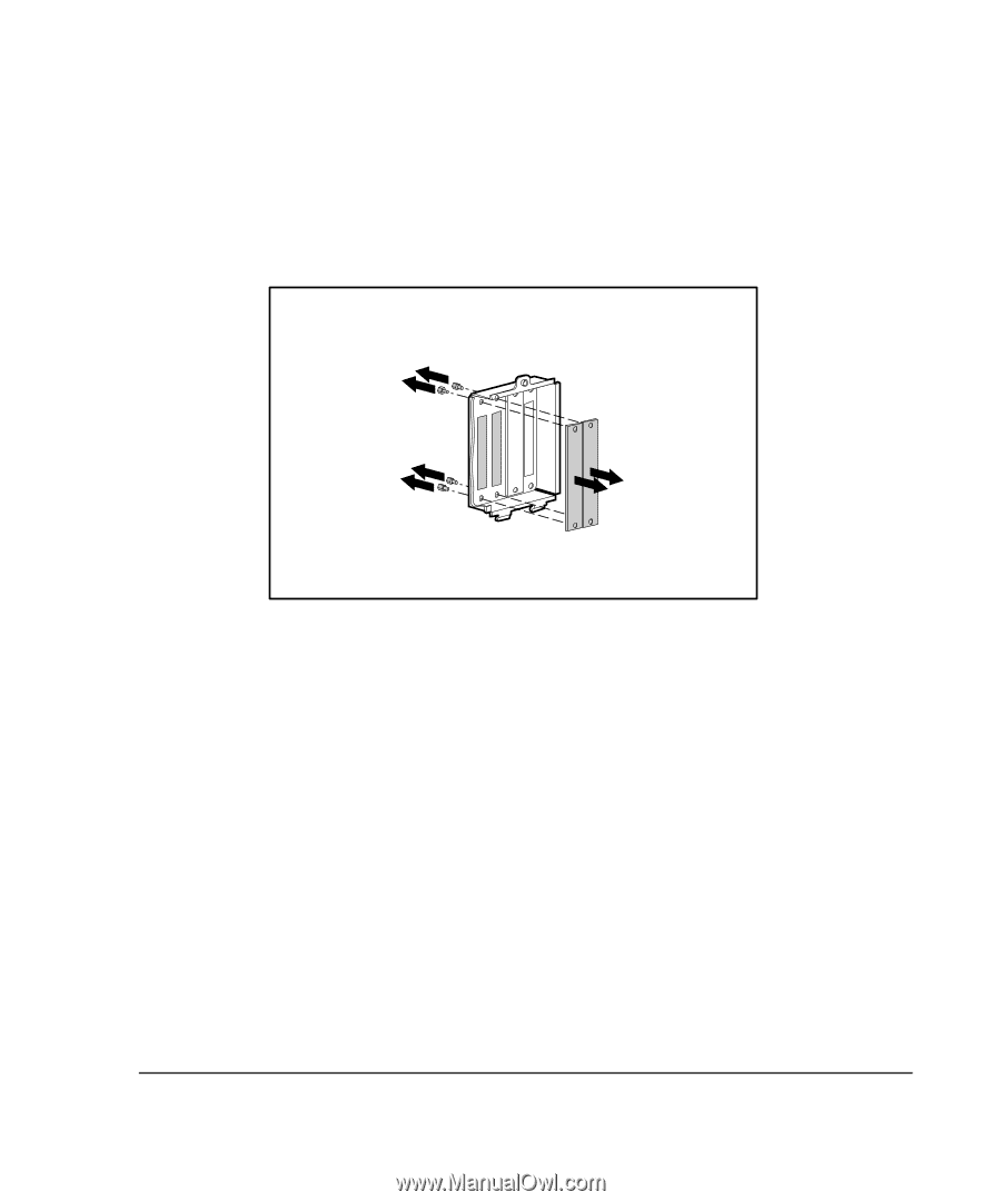
plates as above, exposing the slots.
 |
View all Compaq ProLiant 1000 manuals
Add to My Manuals
Save this manual to your list of manuals |
Page 45 highlights
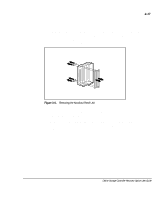
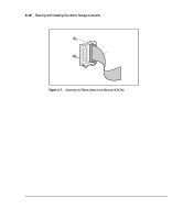
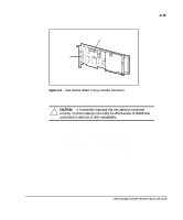
3-17 2. Depending on which server you have, you may need to look on the back of the server case and locate the knockout panel or the plate that covers the hole for the knockout panel. Unscrew the top screw and remove the unit as shown in Figure 3-6. If your server case has integrated knockout slots, expose two of them and skip to step 4. 43 2 1 Figure 3-6. Removing the Knockout Panel Unit 3. Using either the knockout panel included with the Recovery Server Option /U kit or the one removed from the server, remove two of the plates as above, exposing the slots. 4. Locate the internal ribbon cables (part number 199595) and the black case mount bolts. Attach the cables to the external SCSI slots as shown in Figure 3-7. Online Storage Controller Recovery Option User Guide
-
 1
1 -
2
-
3
-
4
-
5
-
6
-
7
-
8
-
9
-
10
-
11
-
12
-
13
-
14
-
15
-
16
-
17
-
18
-
19
-
20
-
21
-
22
-
23
-
24
-
25
-
26
-
27
-
28
-
29
-
30
-
31
-
32
-
33
-
34
-
35
-
36
-
37
-
38
-
39
-
 40
40 -
 41
41 -
 42
42 -
 43
43 -
 44
44 -
 45
45 -
 46
46 -
 47
47 -
 48
48 -
 49
49 -
 50
50 -
51
-
52
-
53
-
54
-
55
-
56
-
57
-
58
-
59
-
60
-
61
-
62
-
63
-
64
-
65
-
66
-
67
-
68
-
69
-
70
-
71
-
72
-
73
-
74
-
75
-
76
-
77
-
78
-
79
-
80
-
81
-
82
-
83
-
84
-
85
-
86
-
87
-
88
-
89
 |
 |