HP StorageWorks 2/32 SAN switch 2/32 version 4.0.x installation guide - Page 65
LEDs on the Non-Port Side of the SAN Switch 2/32, One Port Readiness LED on right side
 |
View all HP StorageWorks 2/32 manuals
Add to My Manuals
Save this manual to your list of manuals |
Page 65 highlights
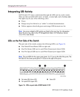
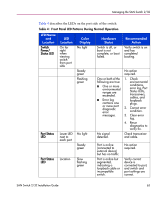
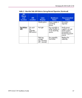
Managing the SAN Switch 2/32 Table 4: Front Panel LED Patterns During Normal Operation (Continued) LED Name and Location Port Status LED (continued) LED Location Location (continued ) Color Display Alternating green and orange Port Speed LED Above No light each port, on right Steady green Hardware Status Port is bypassed. The port is transmitting/ receiving at 1 Gbps. The port is transmitting/ receiving at 2 Gbps. Recommended Action Reset the port from a management station or check configuration of the Fibre Channel loop. No action required. No action required. LEDs on the Non-Port Side of the SAN Switch 2/32 The non-port side of the switch contains the following LEDs, see Figure 17: ■ One Port Readiness LED on right side ■ One Power Supply LED next to the AC power switch on each power supply ■ One Fan Failure LED at the top of each fan assembly (inside the bezel) 1 2 3 SHR-2579A 1 Power supply LED 2 Fan failure LED 3 Port readiness LED Figure 17: LEDs on non-port side of SAN Switch 2/32 Table 5 describes the LEDs on the non-port side of the switch. SAN Switch 2/32 Installation Guide 65
-
 1
1 -
2
-
3
-
4
-
5
-
6
-
7
-
8
-
9
-
10
-
11
-
12
-
13
-
14
-
15
-
16
-
17
-
18
-
19
-
20
-
21
-
22
-
23
-
24
-
25
-
26
-
27
-
28
-
29
-
30
-
31
-
32
-
33
-
34
-
35
-
36
-
37
-
38
-
39
-
40
-
41
-
42
-
43
-
44
-
45
-
46
-
47
-
48
-
49
-
50
-
51
-
52
-
53
-
54
-
55
-
56
-
57
-
58
-
59
-
 60
60 -
 61
61 -
 62
62 -
 63
63 -
 64
64 -
 65
65 -
 66
66 -
 67
67 -
 68
68 -
 69
69 -
 70
70 -
71
-
72
-
73
-
74
-
75
-
76
-
77
-
78
-
79
-
80
-
81
-
82
-
83
-
84
-
85
-
86
-
87
-
88
-
89
-
90
-
91
-
92
-
93
-
94
-
95
-
96
-
97
-
98
-
99
-
100
-
101
-
102
-
103
-
104
-
105
-
106
-
107
-
108
-
109
-
110
-
111
-
112
-
113
-
114
-
115
-
116
-
117
-
118
-
119
-
120
-
121
-
122
-
123
-
124
-
125
-
126
 |
 |
