HP StorageWorks 4/16 HP StorageWorks DC and DC04 SAN Backbone Director Switche - Page 134
Installing the DC04 SAN Director in the cabinet, Table 28
 |
View all HP StorageWorks 4/16 manuals
Add to My Manuals
Save this manual to your list of manuals |
Page 134 highlights
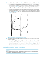
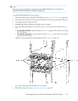
5. Secure the top-rail assembly (A in Figure 39, page 130) to the air-duct assembly. (See Figure 43). a. You can adjust the top-rail assembly to a length of 68.58 to 78.74 cm (27 to 31 inches) to accommodate the cabinet size. To lengthen or shorten the top-rail assembly, loosen the two 6-32 screws (I-3 in Figure 39, page 130) and adjust the top-rail assembly to the desired length. The length will be approximately the length of the adjustable shelf. Once adjusted, tighten the two 6-32 screws. b. Insert the top-rail assembly into the air-duct assembly and then secure the top-rail assembly to the air-duct assembly with two 6-32 screws, one screw on each side of the air-duct assembly (I-1 and I-2 in Figure 39, page 130). Tighten screws according to the specifications listed in Table 28, page 130. Figure 43 Securing the top-rail assembly in the cabinet 6. Secure the top-rail assembly to the cabinet with four 10-32 screws, two screws on each end of the top-rail assembly. • For rails with round holes-Use two 10-32 screws with washers (E in Figure 39, page 130) on each end of the top-rail assembly. • For rails with square holes-Use two standard 10-32 screws (D in Figure 39, page 130) with blue Loctite on the threads and alignment washers (H in Figure 39, page 130) on each end of the top-rail assembly. Installing the DC04 SAN Director in the cabinet CAUTION: A fully populated DC04 SAN Director weighs 68 kg (150 lb) with four FC8-48 port cards installed (192 ports) and requires a hydraulic or assisted lift to install it. 134 DC04 SAN Director Installation
-
 1
1 -
2
-
3
-
4
-
5
-
6
-
7
-
8
-
9
-
10
-
11
-
12
-
13
-
14
-
15
-
16
-
17
-
18
-
19
-
20
-
21
-
22
-
23
-
24
-
25
-
26
-
27
-
28
-
29
-
30
-
31
-
32
-
33
-
34
-
35
-
36
-
37
-
38
-
39
-
40
-
41
-
42
-
43
-
44
-
45
-
46
-
47
-
48
-
49
-
50
-
51
-
52
-
53
-
54
-
55
-
56
-
57
-
58
-
59
-
60
-
61
-
62
-
63
-
64
-
65
-
66
-
67
-
68
-
69
-
70
-
71
-
72
-
73
-
74
-
75
-
76
-
77
-
78
-
79
-
80
-
81
-
82
-
83
-
84
-
85
-
86
-
87
-
88
-
89
-
90
-
91
-
92
-
93
-
94
-
95
-
96
-
97
-
98
-
99
-
100
-
101
-
102
-
103
-
104
-
105
-
106
-
107
-
108
-
109
-
110
-
111
-
112
-
113
-
114
-
115
-
116
-
117
-
118
-
119
-
120
-
121
-
122
-
123
-
124
-
125
-
126
-
127
-
128
-
 129
129 -
 130
130 -
 131
131 -
 132
132 -
 133
133 -
 134
134 -
 135
135 -
 136
136 -
 137
137 -
 138
138 -
 139
139 -
140
-
141
-
142
-
143
-
144
-
145
-
146
-
147
-
148
-
149
-
150
-
151
-
152
-
153
-
154
-
155
-
156
-
157
-
158
-
159
-
160
-
161
-
162
-
163
-
164
-
165
-
166
-
167
-
168
-
169
-
170
-
171
-
172
-
173
-
174
-
175
-
176
-
177
-
178
-
179
-
180
-
181
-
182
-
183
-
184
-
185
-
186
-
187
-
188
-
189
-
190
-
191
-
192
-
193
-
194
-
195
-
196
-
197
-
198
-
199
-
200
-
201
-
202
-
203
-
204
-
205
-
206
-
207
-
208
-
209
-
210
-
211
-
212
-
213
-
214
-
215
-
216
-
217
-
218
-
219
-
220
-
221
-
222
-
223
-
224
-
225
-
226
-
227
-
228
-
229
-
230
-
231
-
232
-
233
-
234
-
235
-
236
-
237
-
238
-
239
-
240
-
241
-
242
-
243
-
244
-
245
-
246
-
247
-
248
-
249
-
250
-
251
-
252
-
253
-
254
-
255
-
256
 |
 |
