HP StorageWorks 4/16 HP StorageWorks DC and DC04 SAN Backbone Director Switche - Page 184
Replacing a power supply, DC04 SAN Director.
 |
View all HP StorageWorks 4/16 manuals
Add to My Manuals
Save this manual to your list of manuals |
Page 184 highlights
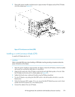
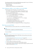
8. Replace the chassis door. See "Installing the chassis door" on page 170. Replacing a power supply The DC04 SAN Director can continue operating during the replacement if at least one power supply continues operating. The replacement procedure for each power supply takes less than five minutes. A power supply unit or filler panel is required for the power supply replacement. Figure 69 shows the location and identification of the power supplies. Figure 69 Power supply identification 1. Power supply 1 (PS1) 2. Power supply 2 (PS2) Removing a power supply To remove a power supply: CAUTION: Wear a grounded ESD strap when handling DC04 SAN Director components. The DC04 SAN Director chassis provides a grounding connection above the power connectors. Also, store ESD-sensitive components in antistatic packaging. 1. If the DC04 SAN Director is not operating during the replacement procedure, go to step 2. If the DC04 SAN Director is going to continue operating during the replacement, check the power LEDs to verify that the minimum number of power supplies is functioning. A fully populated DC04 SAN Director requires a minimum of one power supply slot at all times to ensure power to the DC04 SAN Director. 2. Turn off the power switch. 3. Remove the power cord. 4. Loosen the thumb screw. 5. Grasp the handle and pull, sliding the power supply from the chassis and supporting the power supply from beneath as you remove it (see Figure 70). 6. If you are not replacing the power supply, insert a filler panel into the slot. Installing a power supply To install a power supply: 1. Remove any filler panel. 184 Replacing DC04 SAN Director field-replaceable units (FRUs)
-
 1
1 -
2
-
3
-
4
-
5
-
6
-
7
-
8
-
9
-
10
-
11
-
12
-
13
-
14
-
15
-
16
-
17
-
18
-
19
-
20
-
21
-
22
-
23
-
24
-
25
-
26
-
27
-
28
-
29
-
30
-
31
-
32
-
33
-
34
-
35
-
36
-
37
-
38
-
39
-
40
-
41
-
42
-
43
-
44
-
45
-
46
-
47
-
48
-
49
-
50
-
51
-
52
-
53
-
54
-
55
-
56
-
57
-
58
-
59
-
60
-
61
-
62
-
63
-
64
-
65
-
66
-
67
-
68
-
69
-
70
-
71
-
72
-
73
-
74
-
75
-
76
-
77
-
78
-
79
-
80
-
81
-
82
-
83
-
84
-
85
-
86
-
87
-
88
-
89
-
90
-
91
-
92
-
93
-
94
-
95
-
96
-
97
-
98
-
99
-
100
-
101
-
102
-
103
-
104
-
105
-
106
-
107
-
108
-
109
-
110
-
111
-
112
-
113
-
114
-
115
-
116
-
117
-
118
-
119
-
120
-
121
-
122
-
123
-
124
-
125
-
126
-
127
-
128
-
129
-
130
-
131
-
132
-
133
-
134
-
135
-
136
-
137
-
138
-
139
-
140
-
141
-
142
-
143
-
144
-
145
-
146
-
147
-
148
-
149
-
150
-
151
-
152
-
153
-
154
-
155
-
156
-
157
-
158
-
159
-
160
-
161
-
162
-
163
-
164
-
165
-
166
-
167
-
168
-
169
-
170
-
171
-
172
-
173
-
174
-
175
-
176
-
177
-
178
-
 179
179 -
 180
180 -
 181
181 -
 182
182 -
 183
183 -
 184
184 -
 185
185 -
 186
186 -
 187
187 -
 188
188 -
 189
189 -
190
-
191
-
192
-
193
-
194
-
195
-
196
-
197
-
198
-
199
-
200
-
201
-
202
-
203
-
204
-
205
-
206
-
207
-
208
-
209
-
210
-
211
-
212
-
213
-
214
-
215
-
216
-
217
-
218
-
219
-
220
-
221
-
222
-
223
-
224
-
225
-
226
-
227
-
228
-
229
-
230
-
231
-
232
-
233
-
234
-
235
-
236
-
237
-
238
-
239
-
240
-
241
-
242
-
243
-
244
-
245
-
246
-
247
-
248
-
249
-
250
-
251
-
252
-
253
-
254
-
255
-
256
 |
 |
