HP StorageWorks 4/16 HP StorageWorks DC and DC04 SAN Backbone Director Switche - Page 182
How to determine whether or not to replace a core switch blade, Removing a core switch blade
 |
View all HP StorageWorks 4/16 manuals
Add to My Manuals
Save this manual to your list of manuals |
Page 182 highlights
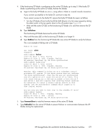
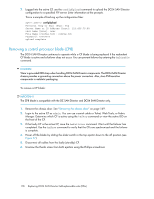
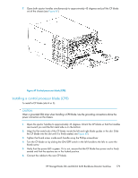
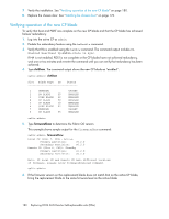
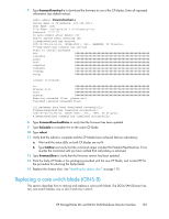
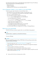
The replacement procedure for the core switch blade takes approximately 30 minutes. The following items are required for the core switch blade replacement: • ESD grounding strap • Phillips #2 screwdriver • Replacement DC04 SAN Director core switch blade (CR4S-8) How to determine whether or not to replace a core switch blade The following events might indicate that a core switch blade is faulty: • The status LED on the core switch blade is lit amber, or the power LED is not lit. • The slotShow command does not show that the core switch blade is enabled. • The haShow command indicates an error. • Any of the following messages is displayed in the error log: • Slot unknown message relating to a core switch blade slot • core switch blade errors or I2C timeouts • FRU: FRU_FAULTY messages for a core switch blade • Configuration loader messages or Sys PCI config messages • Generic system driver messages (FABSYS) • Platform system driver messages (Platform) • EM messages that indicate a problem with a core switch blade • Function fail messages for the core switch blade master For more information about error messages, refer to the Fabric OS Message Reference. Removing a core switch blade The DC04 SAN Director continues to operate while a core switch blade is being replaced. NOTE: The CR4S-8 blade is compatible only with the DC04 SAN Director. To remove a CR blade: CAUTION: Wear a grounded ESD strap when handling a CR4S-8 blade. Use the grounding connections above the power connectors on the chassis. 1. Remove the chassis door. See "Removing the chassis door" on page 169. 2. Power off the blade by sliding the slider switch in the left ejector to the right to the off position (see Figure 68). 3. Disconnect cables from the faulty core switch blade. 4. Unscrew the thumb screw from both ejectors using the Phillips screwdriver. 5. Open both ejector handles simultaneously to approximately 45 degrees and pull the core switch blade out of the chassis (see Figure 68). 182 Replacing DC04 SAN Director field-replaceable units (FRUs)
-
 1
1 -
2
-
3
-
4
-
5
-
6
-
7
-
8
-
9
-
10
-
11
-
12
-
13
-
14
-
15
-
16
-
17
-
18
-
19
-
20
-
21
-
22
-
23
-
24
-
25
-
26
-
27
-
28
-
29
-
30
-
31
-
32
-
33
-
34
-
35
-
36
-
37
-
38
-
39
-
40
-
41
-
42
-
43
-
44
-
45
-
46
-
47
-
48
-
49
-
50
-
51
-
52
-
53
-
54
-
55
-
56
-
57
-
58
-
59
-
60
-
61
-
62
-
63
-
64
-
65
-
66
-
67
-
68
-
69
-
70
-
71
-
72
-
73
-
74
-
75
-
76
-
77
-
78
-
79
-
80
-
81
-
82
-
83
-
84
-
85
-
86
-
87
-
88
-
89
-
90
-
91
-
92
-
93
-
94
-
95
-
96
-
97
-
98
-
99
-
100
-
101
-
102
-
103
-
104
-
105
-
106
-
107
-
108
-
109
-
110
-
111
-
112
-
113
-
114
-
115
-
116
-
117
-
118
-
119
-
120
-
121
-
122
-
123
-
124
-
125
-
126
-
127
-
128
-
129
-
130
-
131
-
132
-
133
-
134
-
135
-
136
-
137
-
138
-
139
-
140
-
141
-
142
-
143
-
144
-
145
-
146
-
147
-
148
-
149
-
150
-
151
-
152
-
153
-
154
-
155
-
156
-
157
-
158
-
159
-
160
-
161
-
162
-
163
-
164
-
165
-
166
-
167
-
168
-
169
-
170
-
171
-
172
-
173
-
174
-
175
-
176
-
 177
177 -
 178
178 -
 179
179 -
 180
180 -
 181
181 -
 182
182 -
 183
183 -
 184
184 -
 185
185 -
 186
186 -
 187
187 -
188
-
189
-
190
-
191
-
192
-
193
-
194
-
195
-
196
-
197
-
198
-
199
-
200
-
201
-
202
-
203
-
204
-
205
-
206
-
207
-
208
-
209
-
210
-
211
-
212
-
213
-
214
-
215
-
216
-
217
-
218
-
219
-
220
-
221
-
222
-
223
-
224
-
225
-
226
-
227
-
228
-
229
-
230
-
231
-
232
-
233
-
234
-
235
-
236
-
237
-
238
-
239
-
240
-
241
-
242
-
243
-
244
-
245
-
246
-
247
-
248
-
249
-
250
-
251
-
252
-
253
-
254
-
255
-
256
 |
 |
