HP StorageWorks 4/16 HP StorageWorks DC and DC04 SAN Backbone Director Switche - Page 78
Replacing a Director blade filler panel, Removing a filler panel
 |
View all HP StorageWorks 4/16 manuals
Add to My Manuals
Save this manual to your list of manuals |
Page 78 highlights
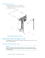
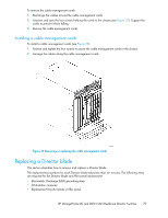
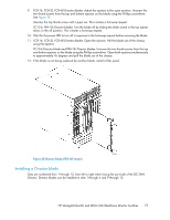
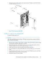
CAUTION: Wear a grounded ESD strap when handling a Director blade. Use the grounding connections above the power connectors on the chassis. 1. Orient the blade so that the ports are at the front of the chassis and the flat side of the blade is on the left. See Figure 28. 2. FC8-16, FC8-32, FC8-48 Director blades: Adjust the ejectors to the open position, align the flat side of the blade inside the upper and lower rail guides in the slot, and slide the blade into the slot until it is firmly seated. See Figure 28. FC10-6 Director blade and FR4-18i Director blade: Open the ejectors to approximately 45 degrees, align the flat side of the blade inside the upper and lower rail guides in the slot, and slide the blade into the slot, with slight pressure to the left, until it is firmly seated. 3. FC8-16, FC8-32, FC8-48 Director blades: Adjust the ejectors to the closed position by pulling them away from the center of the blade. FC10-6 Director blade: Close the ejectors by pushing the handles toward the center of the blade until the ejectors lock. The levering action of the handles seats the blade in the slot. 4. FC8-16, FC8-32, FC8-48 Director blades: Adjust the ejectors to the closed position by pulling them away from the center of the blade. FC10-6 Director blade and FR4-18i Director blade: a. Tighten the thumb screw inside each handle using the Phillips screwdriver. See Figure 28. b. Turn the blade on by sliding the slider switch in the top ejector up, covering the thumb screw. 5. Verify that the power LED on the blade is displaying a steady green light. If it does not turn on, ensure that the blade is firmly seated. 6. Install the SFP or XFP (FC10-6 only) transceivers and cables in the blade. 7. Group and route the cables. 8. Replace the chassis door. See "Installing the chassis door" on page 74. Replacing a Director blade filler panel This section describes how to remove and replace a Director blade filler panel (see Figure 29). Removing a filler panel CAUTION: A filler panel should be removed only when being replaced with a Director blade, or new filler panel. Any slot that is not occupied by a Director blade should be occupied by a filler panel to ensure correct cooling of the chassis and protection from dust. To remove a filler panel: 1. Remove the chassis door. See "Removing the chassis door" on page 73. 2. Unscrew the thumb screw at the bottom of the panel using the Phillips screwdriver. 78 Replacing DC SAN Director field-replaceable units (FRUs)
-
 1
1 -
2
-
3
-
4
-
5
-
6
-
7
-
8
-
9
-
10
-
11
-
12
-
13
-
14
-
15
-
16
-
17
-
18
-
19
-
20
-
21
-
22
-
23
-
24
-
25
-
26
-
27
-
28
-
29
-
30
-
31
-
32
-
33
-
34
-
35
-
36
-
37
-
38
-
39
-
40
-
41
-
42
-
43
-
44
-
45
-
46
-
47
-
48
-
49
-
50
-
51
-
52
-
53
-
54
-
55
-
56
-
57
-
58
-
59
-
60
-
61
-
62
-
63
-
64
-
65
-
66
-
67
-
68
-
69
-
70
-
71
-
72
-
 73
73 -
 74
74 -
 75
75 -
 76
76 -
 77
77 -
 78
78 -
 79
79 -
 80
80 -
 81
81 -
 82
82 -
 83
83 -
84
-
85
-
86
-
87
-
88
-
89
-
90
-
91
-
92
-
93
-
94
-
95
-
96
-
97
-
98
-
99
-
100
-
101
-
102
-
103
-
104
-
105
-
106
-
107
-
108
-
109
-
110
-
111
-
112
-
113
-
114
-
115
-
116
-
117
-
118
-
119
-
120
-
121
-
122
-
123
-
124
-
125
-
126
-
127
-
128
-
129
-
130
-
131
-
132
-
133
-
134
-
135
-
136
-
137
-
138
-
139
-
140
-
141
-
142
-
143
-
144
-
145
-
146
-
147
-
148
-
149
-
150
-
151
-
152
-
153
-
154
-
155
-
156
-
157
-
158
-
159
-
160
-
161
-
162
-
163
-
164
-
165
-
166
-
167
-
168
-
169
-
170
-
171
-
172
-
173
-
174
-
175
-
176
-
177
-
178
-
179
-
180
-
181
-
182
-
183
-
184
-
185
-
186
-
187
-
188
-
189
-
190
-
191
-
192
-
193
-
194
-
195
-
196
-
197
-
198
-
199
-
200
-
201
-
202
-
203
-
204
-
205
-
206
-
207
-
208
-
209
-
210
-
211
-
212
-
213
-
214
-
215
-
216
-
217
-
218
-
219
-
220
-
221
-
222
-
223
-
224
-
225
-
226
-
227
-
228
-
229
-
230
-
231
-
232
-
233
-
234
-
235
-
236
-
237
-
238
-
239
-
240
-
241
-
242
-
243
-
244
-
245
-
246
-
247
-
248
-
249
-
250
-
251
-
252
-
253
-
254
-
255
-
256
 |
 |
