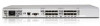
HP StorageWorks 4/16 HP StorageWorks DC and DC04 SAN Backbone Director Switche - Page 88
Replacing a power supply
 |
View all HP StorageWorks 4/16 manuals
Add to My Manuals
Save this manual to your list of manuals |
Page 88 highlights
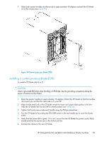
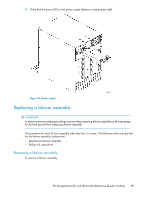
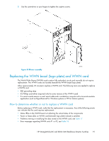
4. Turn the core switch blade on by sliding the ON/OFF switch in the top handle up, to cover the thumb screw. 5. Verify that the power LED is green (this may require a few seconds). If not, ensure that the core switch blade has power and is firmly seated and that the ejectors are in the locked position. 6. Connect to the new core switch blade. 7. Pack the faulty core switch blade in the packaging provided with the new core switch blade, and contact the DC04 SAN Director supplier for the procedure for returning the faulty blade. 8. Replace the chassis door. See "Installing the chassis door" on page 74. Replacing a power supply The DC SAN Director can continue operating during the replacement if at least one power supply continues operating. The replacement procedure for each power supply takes less than five minutes. A power supply unit or filler panel is required for the power supply replacement. Removing a power supply To remove a power supply: CAUTION: Wear a grounded ESD strap when handling DC SAN Director components. The Director chassis provides a grounding connection above the power connectors. Also, store ESD-sensitive components in antistatic packaging. 1. If the DC SAN Director is not operating during the replacement procedure, go to step 2. If the DC SAN Director is going to continue operating during the replacement, check the power LEDs to verify that the minimum number of power supplies is functioning. A fully populated DC SAN Director requires a minimum of one power supply slot at all times to ensure power to the DC SAN Director. 2. Loosen the thumb screw. 3. Pull the handle out and down (see Figure 32). 4. Support the power supply from beneath. Use the handle to remove the power supply out of the chassis. 5. If you are not replacing the power supply, insert a filler panel into the slot. Installing a power supply To install a power supply: 1. Remove any filler panel. 2. Insert the power supply into the slot and push the handle up. Verify that the power supply is seated by gently pulling on the handle (see Figure 32). 3. Tighten the thumb screw. 88 Replacing DC SAN Director field-replaceable units (FRUs)
-
 1
1 -
2
-
3
-
4
-
5
-
6
-
7
-
8
-
9
-
10
-
11
-
12
-
13
-
14
-
15
-
16
-
17
-
18
-
19
-
20
-
21
-
22
-
23
-
24
-
25
-
26
-
27
-
28
-
29
-
30
-
31
-
32
-
33
-
34
-
35
-
36
-
37
-
38
-
39
-
40
-
41
-
42
-
43
-
44
-
45
-
46
-
47
-
48
-
49
-
50
-
51
-
52
-
53
-
54
-
55
-
56
-
57
-
58
-
59
-
60
-
61
-
62
-
63
-
64
-
65
-
66
-
67
-
68
-
69
-
70
-
71
-
72
-
73
-
74
-
75
-
76
-
77
-
78
-
79
-
80
-
81
-
82
-
 83
83 -
 84
84 -
 85
85 -
 86
86 -
 87
87 -
 88
88 -
 89
89 -
 90
90 -
 91
91 -
 92
92 -
 93
93 -
94
-
95
-
96
-
97
-
98
-
99
-
100
-
101
-
102
-
103
-
104
-
105
-
106
-
107
-
108
-
109
-
110
-
111
-
112
-
113
-
114
-
115
-
116
-
117
-
118
-
119
-
120
-
121
-
122
-
123
-
124
-
125
-
126
-
127
-
128
-
129
-
130
-
131
-
132
-
133
-
134
-
135
-
136
-
137
-
138
-
139
-
140
-
141
-
142
-
143
-
144
-
145
-
146
-
147
-
148
-
149
-
150
-
151
-
152
-
153
-
154
-
155
-
156
-
157
-
158
-
159
-
160
-
161
-
162
-
163
-
164
-
165
-
166
-
167
-
168
-
169
-
170
-
171
-
172
-
173
-
174
-
175
-
176
-
177
-
178
-
179
-
180
-
181
-
182
-
183
-
184
-
185
-
186
-
187
-
188
-
189
-
190
-
191
-
192
-
193
-
194
-
195
-
196
-
197
-
198
-
199
-
200
-
201
-
202
-
203
-
204
-
205
-
206
-
207
-
208
-
209
-
210
-
211
-
212
-
213
-
214
-
215
-
216
-
217
-
218
-
219
-
220
-
221
-
222
-
223
-
224
-
225
-
226
-
227
-
228
-
229
-
230
-
231
-
232
-
233
-
234
-
235
-
236
-
237
-
238
-
239
-
240
-
241
-
242
-
243
-
244
-
245
-
246
-
247
-
248
-
249
-
250
-
251
-
252
-
253
-
254
-
255
-
256
 |
 |
