HP StorageWorks 4/16 HP StorageWorks DC and DC04 SAN Backbone Director Switche - Page 87
Installing a core switch blade (CR8), Core switch blade CR8
 |
View all HP StorageWorks 4/16 manuals
Add to My Manuals
Save this manual to your list of manuals |
Page 87 highlights
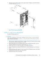
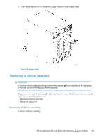
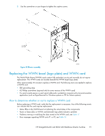
2. Power off the blade by sliding the slider switch in the top ejector down to the off position (see Figure 31). 3. Disconnect cables from the faulty core switch blade. 4. Unscrew the thumb screw from both ejectors using the Phillips screwdriver. 5. Open both ejector handles simultaneously to approximately 45 degrees and pull the core switch blade out of the chassis (see Figure 31). Figure 31 Core switch blade (CR8) 26386a Installing a core switch blade (CR8) To install a CR blade (slot 5 or 6): CAUTION: Wear a grounded ESD strap when handling a CR8 blade. Use the grounding connections above the power connectors on the chassis. 1. Open the ejector handles to approximately 45 degrees, and then orient the CP blade so that the handles are toward you and the flat metal side is on your left. 2. Align the flat metal side of the core switch blade inside the lower and upper blade guides in the slot, and then slide the core switch blade into the slot until it is firmly seated (see Figure 31). 3. Tighten the thumb screw inside each handle using the Phillips screwdriver. HP StorageWorks DC and DC04 SAN Backbone Director Switches 87
-
 1
1 -
2
-
3
-
4
-
5
-
6
-
7
-
8
-
9
-
10
-
11
-
12
-
13
-
14
-
15
-
16
-
17
-
18
-
19
-
20
-
21
-
22
-
23
-
24
-
25
-
26
-
27
-
28
-
29
-
30
-
31
-
32
-
33
-
34
-
35
-
36
-
37
-
38
-
39
-
40
-
41
-
42
-
43
-
44
-
45
-
46
-
47
-
48
-
49
-
50
-
51
-
52
-
53
-
54
-
55
-
56
-
57
-
58
-
59
-
60
-
61
-
62
-
63
-
64
-
65
-
66
-
67
-
68
-
69
-
70
-
71
-
72
-
73
-
74
-
75
-
76
-
77
-
78
-
79
-
80
-
81
-
 82
82 -
 83
83 -
 84
84 -
 85
85 -
 86
86 -
 87
87 -
 88
88 -
 89
89 -
 90
90 -
 91
91 -
 92
92 -
93
-
94
-
95
-
96
-
97
-
98
-
99
-
100
-
101
-
102
-
103
-
104
-
105
-
106
-
107
-
108
-
109
-
110
-
111
-
112
-
113
-
114
-
115
-
116
-
117
-
118
-
119
-
120
-
121
-
122
-
123
-
124
-
125
-
126
-
127
-
128
-
129
-
130
-
131
-
132
-
133
-
134
-
135
-
136
-
137
-
138
-
139
-
140
-
141
-
142
-
143
-
144
-
145
-
146
-
147
-
148
-
149
-
150
-
151
-
152
-
153
-
154
-
155
-
156
-
157
-
158
-
159
-
160
-
161
-
162
-
163
-
164
-
165
-
166
-
167
-
168
-
169
-
170
-
171
-
172
-
173
-
174
-
175
-
176
-
177
-
178
-
179
-
180
-
181
-
182
-
183
-
184
-
185
-
186
-
187
-
188
-
189
-
190
-
191
-
192
-
193
-
194
-
195
-
196
-
197
-
198
-
199
-
200
-
201
-
202
-
203
-
204
-
205
-
206
-
207
-
208
-
209
-
210
-
211
-
212
-
213
-
214
-
215
-
216
-
217
-
218
-
219
-
220
-
221
-
222
-
223
-
224
-
225
-
226
-
227
-
228
-
229
-
230
-
231
-
232
-
233
-
234
-
235
-
236
-
237
-
238
-
239
-
240
-
241
-
242
-
243
-
244
-
245
-
246
-
247
-
248
-
249
-
250
-
251
-
252
-
253
-
254
-
255
-
256
 |
 |
