HP StorageWorks 4/16 HP StorageWorks DC and DC04 SAN Backbone Director Switche - Page 171
Installing a cable management finger assembly, Replacing DC04 SAN Director port and application blades
 |
View all HP StorageWorks 4/16 manuals
Add to My Manuals
Save this manual to your list of manuals |
Page 171 highlights
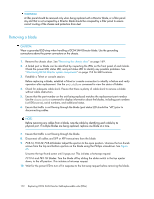
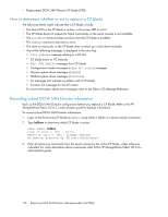
2. Unscrew and save the three screws holding the finger assembly to the rack upright (see Figure 64). Support the assembly to prevent it from falling. 3. Remove the cable management finger assembly. 4. If necessary, repeat step 1 through step 3 for the other finger assembly. Installing a cable management finger assembly To install a cable management finger assembly (see Figure 64): 1. Position and tighten the three screws to secure the vertical cable management finger assembly to the rack upright. 2. Arrange the cables along the cable management finger assembly. 3. If necessary, repeat step 1 and step 2 for the other cable management assembly. Figure 64 Removing or replacing the cable management finger assembly Replacing DC04 SAN Director port and application blades This section describes how to remove and replace a DC04 SAN Director port or application blade. The replacement procedure for each blade takes less than ten minutes. The following items are required: • Electrostatic Discharge (ESD) grounding strap • Workstation computer • Replacement DC04 SAN Director blade or filler panel • Phillips screwdriver • Small form-factor pluggable (SFP) or extended form-factor pluggable (XFP, FC10-6 Director blade only) transceivers (as needed) • Optical cables (as needed) HP StorageWorks DC and DC04 SAN Backbone Director Switches 171
-
 1
1 -
2
-
3
-
4
-
5
-
6
-
7
-
8
-
9
-
10
-
11
-
12
-
13
-
14
-
15
-
16
-
17
-
18
-
19
-
20
-
21
-
22
-
23
-
24
-
25
-
26
-
27
-
28
-
29
-
30
-
31
-
32
-
33
-
34
-
35
-
36
-
37
-
38
-
39
-
40
-
41
-
42
-
43
-
44
-
45
-
46
-
47
-
48
-
49
-
50
-
51
-
52
-
53
-
54
-
55
-
56
-
57
-
58
-
59
-
60
-
61
-
62
-
63
-
64
-
65
-
66
-
67
-
68
-
69
-
70
-
71
-
72
-
73
-
74
-
75
-
76
-
77
-
78
-
79
-
80
-
81
-
82
-
83
-
84
-
85
-
86
-
87
-
88
-
89
-
90
-
91
-
92
-
93
-
94
-
95
-
96
-
97
-
98
-
99
-
100
-
101
-
102
-
103
-
104
-
105
-
106
-
107
-
108
-
109
-
110
-
111
-
112
-
113
-
114
-
115
-
116
-
117
-
118
-
119
-
120
-
121
-
122
-
123
-
124
-
125
-
126
-
127
-
128
-
129
-
130
-
131
-
132
-
133
-
134
-
135
-
136
-
137
-
138
-
139
-
140
-
141
-
142
-
143
-
144
-
145
-
146
-
147
-
148
-
149
-
150
-
151
-
152
-
153
-
154
-
155
-
156
-
157
-
158
-
159
-
160
-
161
-
162
-
163
-
164
-
165
-
 166
166 -
 167
167 -
 168
168 -
 169
169 -
 170
170 -
 171
171 -
 172
172 -
 173
173 -
 174
174 -
 175
175 -
 176
176 -
177
-
178
-
179
-
180
-
181
-
182
-
183
-
184
-
185
-
186
-
187
-
188
-
189
-
190
-
191
-
192
-
193
-
194
-
195
-
196
-
197
-
198
-
199
-
200
-
201
-
202
-
203
-
204
-
205
-
206
-
207
-
208
-
209
-
210
-
211
-
212
-
213
-
214
-
215
-
216
-
217
-
218
-
219
-
220
-
221
-
222
-
223
-
224
-
225
-
226
-
227
-
228
-
229
-
230
-
231
-
232
-
233
-
234
-
235
-
236
-
237
-
238
-
239
-
240
-
241
-
242
-
243
-
244
-
245
-
246
-
247
-
248
-
249
-
250
-
251
-
252
-
253
-
254
-
255
-
256
 |
 |
