Konica Minolta Kodak Truper 3610 User Guide - Page 79
module, then carefully pull it out., at both sides of the module connector to release the DIMM
 |
View all Konica Minolta Kodak Truper 3610 manuals
Add to My Manuals
Save this manual to your list of manuals |
Page 79 highlights
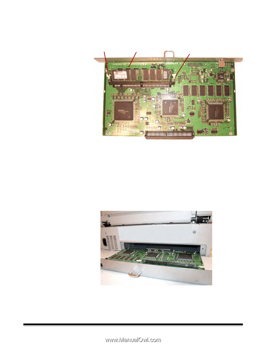
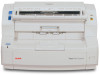
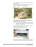
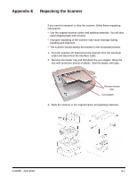
5. Insert the DIMM module into the module connector on the interface board at an angle. 6. Push the module in until it clicks into place and the white tabs on the module connector close around the DIMM module. White tab Indent White tab 7. Be sure the indent on the DIMM module is to the left side when you insert the DIMM module. If the indent is not in this position, the DIMM module will not be inserted properly. NOTE: If you need to remove the DIMM module, pull the white tabs at both sides of the module connector to release the DIMM module, then carefully pull it out. 8. Slide the interface board back into the unit by guiding the board into place along the rails located inside the scanner. 9. Push the board in firmly until it locks into place. 10. Confirm that the interface board is fully inserted and firmly locked in place, then secure the interface board with the two retaining screws. C-2 A-61660 April 2010
-
 1
1 -
2
-
3
-
4
-
5
-
6
-
7
-
8
-
9
-
10
-
11
-
12
-
13
-
14
-
15
-
16
-
17
-
18
-
19
-
20
-
21
-
22
-
23
-
24
-
25
-
26
-
27
-
28
-
29
-
30
-
31
-
32
-
33
-
34
-
35
-
36
-
37
-
38
-
39
-
40
-
41
-
42
-
43
-
44
-
45
-
46
-
47
-
48
-
49
-
50
-
51
-
52
-
53
-
54
-
55
-
56
-
57
-
58
-
59
-
60
-
61
-
62
-
63
-
64
-
65
-
66
-
67
-
68
-
69
-
70
-
71
-
72
-
73
-
 74
74 -
 75
75 -
 76
76 -
 77
77 -
 78
78 -
 79
79 -
 80
80 -
 81
81 -
 82
82 -
 83
83
 |
 |