Kyocera FS-1050 Service Manual - Page 138
Completely blank printout
 |
View all Kyocera FS-1050 manuals
Add to My Manuals
Save this manual to your list of manuals |
Page 138 highlights
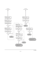
(1) Completely blank printout Check the process unit. • Check that the process unit is inserted correctly. Check the transfer bias potential. • Check the transfer bias output on the high voltage board. This requires removal of the left cover and the test equipment. Replace the high voltage board if high voltage potential is not available on the board (See page 5-13). Check the laser scanner unit. • The scanner components within the scanner may be disordered. Replace the laser scanner unit if necessary (See page 5-28). FS-1050 6-18
-
 1
1 -
2
-
3
-
4
-
5
-
6
-
7
-
8
-
9
-
10
-
11
-
12
-
13
-
14
-
15
-
16
-
17
-
18
-
19
-
20
-
21
-
22
-
23
-
24
-
25
-
26
-
27
-
28
-
29
-
30
-
31
-
32
-
33
-
34
-
35
-
36
-
37
-
38
-
39
-
40
-
41
-
42
-
43
-
44
-
45
-
46
-
47
-
48
-
49
-
50
-
51
-
52
-
53
-
54
-
55
-
56
-
57
-
58
-
59
-
60
-
61
-
62
-
63
-
64
-
65
-
66
-
67
-
68
-
69
-
70
-
71
-
72
-
73
-
74
-
75
-
76
-
77
-
78
-
79
-
80
-
81
-
82
-
83
-
84
-
85
-
86
-
87
-
88
-
89
-
90
-
91
-
92
-
93
-
94
-
95
-
96
-
97
-
98
-
99
-
100
-
101
-
102
-
103
-
104
-
105
-
106
-
107
-
108
-
109
-
110
-
111
-
112
-
113
-
114
-
115
-
116
-
117
-
118
-
119
-
120
-
121
-
122
-
123
-
124
-
125
-
126
-
127
-
128
-
129
-
130
-
131
-
132
-
 133
133 -
 134
134 -
 135
135 -
 136
136 -
 137
137 -
 138
138 -
 139
139 -
 140
140 -
 141
141 -
 142
142 -
 143
143 -
144
-
145
-
146
-
147
-
148
-
149
-
150
-
151
-
152
-
153
-
154
-
155
-
156
-
157
-
158
-
159
-
160
-
161
-
162
-
163
-
164
-
165
-
166
-
167
-
168
-
169
-
170
-
171
-
172
-
173
-
174
-
175
-
176
-
177
 |
 |

6-18
FS-1050
(1) Completely blank printout
Check the process unit.
• Check that the process unit is inserted correctly.
Check the transfer bias potential.
• Check the transfer bias output on the high voltage board. This requires removal of the left cover
and the test equipment. Replace the high voltage board if high voltage potential is not available on
the board (See page 5-13).
Check the laser scanner unit.
• The scanner components within the scanner may be disordered. Replace the laser scanner unit if
necessary (See page 5-28).