Kyocera FS-1050 Service Manual - Page 67
Laser scanner unit, Laser scanner unit
 |
View all Kyocera FS-1050 manuals
Add to My Manuals
Save this manual to your list of manuals |
Page 67 highlights
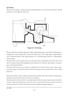
Laser scanner unit 3 2 4 1 6 5 Diversion mirror Figure 4-1-6 Laser scanner unit Name 1 Laser diode 2 Cylindrical lens 3 Polygon mirror (motor) 4 F-theta lens 5 Sensor mirror 6 Pin photo sensor Description Emits diffused, visible laser. Compensates the vertical angle at which the laser beam hits a polygon mirror segment. Has six mirror segments around its hexagonal circumference; each mirror corresponding to one scanned line width on the drum when laser beam scans on it. The f-theta lens equalizes focusing distortion on the far ends of the drum. Bends the very first shot of a laser scan towards the beam detection sensor (6). When shone by the sensor mirror above, this photo-sensor generates a trigger signal for the engine controller to start activating the paper feeding system. FS-1050 4-8
-
 1
1 -
2
-
3
-
4
-
5
-
6
-
7
-
8
-
9
-
10
-
11
-
12
-
13
-
14
-
15
-
16
-
17
-
18
-
19
-
20
-
21
-
22
-
23
-
24
-
25
-
26
-
27
-
28
-
29
-
30
-
31
-
32
-
33
-
34
-
35
-
36
-
37
-
38
-
39
-
40
-
41
-
42
-
43
-
44
-
45
-
46
-
47
-
48
-
49
-
50
-
51
-
52
-
53
-
54
-
55
-
56
-
57
-
58
-
59
-
60
-
61
-
 62
62 -
 63
63 -
 64
64 -
 65
65 -
 66
66 -
 67
67 -
 68
68 -
 69
69 -
 70
70 -
 71
71 -
 72
72 -
73
-
74
-
75
-
76
-
77
-
78
-
79
-
80
-
81
-
82
-
83
-
84
-
85
-
86
-
87
-
88
-
89
-
90
-
91
-
92
-
93
-
94
-
95
-
96
-
97
-
98
-
99
-
100
-
101
-
102
-
103
-
104
-
105
-
106
-
107
-
108
-
109
-
110
-
111
-
112
-
113
-
114
-
115
-
116
-
117
-
118
-
119
-
120
-
121
-
122
-
123
-
124
-
125
-
126
-
127
-
128
-
129
-
130
-
131
-
132
-
133
-
134
-
135
-
136
-
137
-
138
-
139
-
140
-
141
-
142
-
143
-
144
-
145
-
146
-
147
-
148
-
149
-
150
-
151
-
152
-
153
-
154
-
155
-
156
-
157
-
158
-
159
-
160
-
161
-
162
-
163
-
164
-
165
-
166
-
167
-
168
-
169
-
170
-
171
-
172
-
173
-
174
-
175
-
176
-
177
 |
 |
