Kyocera FS-1050 Service Manual - Page 75
Paper feed control, Paper feed control
 |
View all Kyocera FS-1050 manuals
Add to My Manuals
Save this manual to your list of manuals |
Page 75 highlights
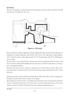
4-2-1 Paper feed control The following diagram shows interconnectivity of the feeding system components including the sensors and rollers. The engine board provides the signals in conjunction with the electrophotography process that is driven by the main board. 8 Fuser unit 6 Exit 7 sensor Power supply board High voltage board Bias board Power train Toner container TK-17 Process unit Drum Developing roller 5 4 3 1 2 Registration sensor MP tray MP feed clutch MP paper sensor Main motor Registration clutch Cassette Paper sensor Feed clutch Cassette Optional paper feeder PF-17 Bias board Main motor HANDSN YC07-2 MPFDRN FEDDRN RESIT PAPERN YC03-2 RESDRN YC04-8 MOTORN YC11-8 EXITN YC09-2 YC04-1 YC12-7 YC12-9 Engine board 1 MP feed roller 5 Transfer roller 2 Feed roller 3 Lower registration roller 4 Upper registration roller 6 Heat roller 7 Lower exit roller 8 Upper exit roller Figure 4-2-2 Paper feed control FS-1050 4-16
-
 1
1 -
2
-
3
-
4
-
5
-
6
-
7
-
8
-
9
-
10
-
11
-
12
-
13
-
14
-
15
-
16
-
17
-
18
-
19
-
20
-
21
-
22
-
23
-
24
-
25
-
26
-
27
-
28
-
29
-
30
-
31
-
32
-
33
-
34
-
35
-
36
-
37
-
38
-
39
-
40
-
41
-
42
-
43
-
44
-
45
-
46
-
47
-
48
-
49
-
50
-
51
-
52
-
53
-
54
-
55
-
56
-
57
-
58
-
59
-
60
-
61
-
62
-
63
-
64
-
65
-
66
-
67
-
68
-
69
-
 70
70 -
 71
71 -
 72
72 -
 73
73 -
 74
74 -
 75
75 -
 76
76 -
 77
77 -
 78
78 -
 79
79 -
 80
80 -
81
-
82
-
83
-
84
-
85
-
86
-
87
-
88
-
89
-
90
-
91
-
92
-
93
-
94
-
95
-
96
-
97
-
98
-
99
-
100
-
101
-
102
-
103
-
104
-
105
-
106
-
107
-
108
-
109
-
110
-
111
-
112
-
113
-
114
-
115
-
116
-
117
-
118
-
119
-
120
-
121
-
122
-
123
-
124
-
125
-
126
-
127
-
128
-
129
-
130
-
131
-
132
-
133
-
134
-
135
-
136
-
137
-
138
-
139
-
140
-
141
-
142
-
143
-
144
-
145
-
146
-
147
-
148
-
149
-
150
-
151
-
152
-
153
-
154
-
155
-
156
-
157
-
158
-
159
-
160
-
161
-
162
-
163
-
164
-
165
-
166
-
167
-
168
-
169
-
170
-
171
-
172
-
173
-
174
-
175
-
176
-
177
 |
 |
