Kyocera FS-1050 Service Manual - Page 84
Polygon motor control circuit, Polygon motor control circuit
 |
View all Kyocera FS-1050 manuals
Add to My Manuals
Save this manual to your list of manuals |
Page 84 highlights
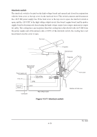
Polygon motor control circuit The main controller board supplies the 1700.8 Hz clock pulse (PLGCLK) via the engine board to the PLL control IC (IC1) for the polygon motor. To begin printing, the engine CPU U01 turns PLGDR to H level, the PLL control IC (IC1) starts to revolve the polygon motor so that the revolution is 17,008 rpm which depends on the PLGCLK clock pulse. When PLL control IC (IC1) finds that the polygon motor is revolving at the rated speed, turns PLGDRN to L level to acknowledge the engine CPU that the rated speed has been achieved. On the contrary, if PLGRDYN does not turn to L level within 8 seconds since PLGDRN has been L level, the printer displays "Call service 4000". Main board PLGCLK Engine board Polygon motor control circuit CPU R35 3 U01 PLGDR 2 +5V Q09 1 R38 GND PLGRDYN R32 1700.8 Hz 2 3 Q10 R41 C18 1 GND +24V + Laser scanner unit Polygon motor PGND 5 4 3 2 1 YC06 PGND +24V PGND PLGDRN PLGRDYN PLGCLK 17,008 rpm PLL control IC (IC1) Figure 4-3-7 Polygon motor control circuit 4-25 FS-1050
-
 1
1 -
2
-
3
-
4
-
5
-
6
-
7
-
8
-
9
-
10
-
11
-
12
-
13
-
14
-
15
-
16
-
17
-
18
-
19
-
20
-
21
-
22
-
23
-
24
-
25
-
26
-
27
-
28
-
29
-
30
-
31
-
32
-
33
-
34
-
35
-
36
-
37
-
38
-
39
-
40
-
41
-
42
-
43
-
44
-
45
-
46
-
47
-
48
-
49
-
50
-
51
-
52
-
53
-
54
-
55
-
56
-
57
-
58
-
59
-
60
-
61
-
62
-
63
-
64
-
65
-
66
-
67
-
68
-
69
-
70
-
71
-
72
-
73
-
74
-
75
-
76
-
77
-
78
-
 79
79 -
 80
80 -
 81
81 -
 82
82 -
 83
83 -
 84
84 -
 85
85 -
 86
86 -
 87
87 -
 88
88 -
 89
89 -
90
-
91
-
92
-
93
-
94
-
95
-
96
-
97
-
98
-
99
-
100
-
101
-
102
-
103
-
104
-
105
-
106
-
107
-
108
-
109
-
110
-
111
-
112
-
113
-
114
-
115
-
116
-
117
-
118
-
119
-
120
-
121
-
122
-
123
-
124
-
125
-
126
-
127
-
128
-
129
-
130
-
131
-
132
-
133
-
134
-
135
-
136
-
137
-
138
-
139
-
140
-
141
-
142
-
143
-
144
-
145
-
146
-
147
-
148
-
149
-
150
-
151
-
152
-
153
-
154
-
155
-
156
-
157
-
158
-
159
-
160
-
161
-
162
-
163
-
164
-
165
-
166
-
167
-
168
-
169
-
170
-
171
-
172
-
173
-
174
-
175
-
176
-
177
 |
 |
