Kyocera FS-1050 Service Manual - Page 69
Development, Development
 |
View all Kyocera FS-1050 manuals
Add to My Manuals
Save this manual to your list of manuals |
Page 69 highlights
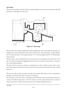
(3) Development The latent image constituted on the drum is developed into a visible image. The developing roller A contains a 3-pole (S-N-S) magnet core B and an aluminum cylinder rotating around the magnet core B. Toner attracts to the developing roller A since it is powdery ink made of black resin bound to iron particles. Doctor blade C, magnetized by magnet D, is positioned approximately 0.3 mm above the developing roller A to constitute a smooth layer of toner in accordance with the roller revolution. C Magnetism N 0.1 mm S E S D 0.3 - 0.4 mm N S AB F Developing bias output 275±5 V DC + AC Bias board YC-B Engine board HVCLK YC302-8 YC11-5 Figure 4-1-8 Development The developing roller A is applied with the AC-weighted, positive DC power source. Toner E on the developing roller A is given a positive charge. The positively charged toner E is then attracted to the areas of the drum F which was exposed to the laser light. (The gap between the drum F and the developing roller A is approximately 0.3 mm.) The non-exposed areas of the drum F repel the positively charged toner as these areas maintain the positive charge. The developing roller A is also AC-biased to ensure contrast in yielding by compensating the toner's attraction and repelling action during development. FS-1050 4-10
-
 1
1 -
2
-
3
-
4
-
5
-
6
-
7
-
8
-
9
-
10
-
11
-
12
-
13
-
14
-
15
-
16
-
17
-
18
-
19
-
20
-
21
-
22
-
23
-
24
-
25
-
26
-
27
-
28
-
29
-
30
-
31
-
32
-
33
-
34
-
35
-
36
-
37
-
38
-
39
-
40
-
41
-
42
-
43
-
44
-
45
-
46
-
47
-
48
-
49
-
50
-
51
-
52
-
53
-
54
-
55
-
56
-
57
-
58
-
59
-
60
-
61
-
62
-
63
-
 64
64 -
 65
65 -
 66
66 -
 67
67 -
 68
68 -
 69
69 -
 70
70 -
 71
71 -
 72
72 -
 73
73 -
 74
74 -
75
-
76
-
77
-
78
-
79
-
80
-
81
-
82
-
83
-
84
-
85
-
86
-
87
-
88
-
89
-
90
-
91
-
92
-
93
-
94
-
95
-
96
-
97
-
98
-
99
-
100
-
101
-
102
-
103
-
104
-
105
-
106
-
107
-
108
-
109
-
110
-
111
-
112
-
113
-
114
-
115
-
116
-
117
-
118
-
119
-
120
-
121
-
122
-
123
-
124
-
125
-
126
-
127
-
128
-
129
-
130
-
131
-
132
-
133
-
134
-
135
-
136
-
137
-
138
-
139
-
140
-
141
-
142
-
143
-
144
-
145
-
146
-
147
-
148
-
149
-
150
-
151
-
152
-
153
-
154
-
155
-
156
-
157
-
158
-
159
-
160
-
161
-
162
-
163
-
164
-
165
-
166
-
167
-
168
-
169
-
170
-
171
-
172
-
173
-
174
-
175
-
176
-
177
 |
 |
