Kyocera FS-1050 Service Manual - Page 87
High voltage board, High voltage board circuit block diagram - fs driver
 |
View all Kyocera FS-1050 manuals
Add to My Manuals
Save this manual to your list of manuals |
Page 87 highlights
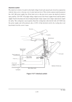
(5) High voltage board The high voltage board contains the high voltage output circuit, interlock switch circuit as well as providing a liaison connection with the power supply board, bias board, and the engine board. Engine board Bias board MHVDR High voltage board High voltage output circuit Control and driver circuit Main charger THVDR, RTHVDR PSEL1, PSEL2 HVISEL +24V2 Control and driver circuit +5V Transfer roller Transfer bias output positive voltage circuit Interlock switch Power supply board +24V2 +24V1 FAN, HEATN, SLEEP ZCROSS, THERM, EXITN +5V Figure 4-3-10 High voltage board circuit block diagram FS-1050 4-28
-
 1
1 -
2
-
3
-
4
-
5
-
6
-
7
-
8
-
9
-
10
-
11
-
12
-
13
-
14
-
15
-
16
-
17
-
18
-
19
-
20
-
21
-
22
-
23
-
24
-
25
-
26
-
27
-
28
-
29
-
30
-
31
-
32
-
33
-
34
-
35
-
36
-
37
-
38
-
39
-
40
-
41
-
42
-
43
-
44
-
45
-
46
-
47
-
48
-
49
-
50
-
51
-
52
-
53
-
54
-
55
-
56
-
57
-
58
-
59
-
60
-
61
-
62
-
63
-
64
-
65
-
66
-
67
-
68
-
69
-
70
-
71
-
72
-
73
-
74
-
75
-
76
-
77
-
78
-
79
-
80
-
81
-
 82
82 -
 83
83 -
 84
84 -
 85
85 -
 86
86 -
 87
87 -
 88
88 -
 89
89 -
 90
90 -
 91
91 -
 92
92 -
93
-
94
-
95
-
96
-
97
-
98
-
99
-
100
-
101
-
102
-
103
-
104
-
105
-
106
-
107
-
108
-
109
-
110
-
111
-
112
-
113
-
114
-
115
-
116
-
117
-
118
-
119
-
120
-
121
-
122
-
123
-
124
-
125
-
126
-
127
-
128
-
129
-
130
-
131
-
132
-
133
-
134
-
135
-
136
-
137
-
138
-
139
-
140
-
141
-
142
-
143
-
144
-
145
-
146
-
147
-
148
-
149
-
150
-
151
-
152
-
153
-
154
-
155
-
156
-
157
-
158
-
159
-
160
-
161
-
162
-
163
-
164
-
165
-
166
-
167
-
168
-
169
-
170
-
171
-
172
-
173
-
174
-
175
-
176
-
177
 |
 |

4-28
FS-1050
(5) High voltage board
The high voltage board contains the high voltage output circuit, interlock switch circuit as well as
providing a liaison connection with the power supply board, bias board, and the engine board.
Figure 4-3-10 High voltage board circuit block diagram
Control
and
driver
circuit
Transfer bias
output
positive voltage
circuit
MHVDR
THVDR,
RTHVDR
PSEL1,
PSEL2
HVISEL
+24V2
+24V2
+24V1
+5V
+5V
ZCROSS,
THERM, EXITN
Interlock switch
High voltage board
Bias board
Power supply board
Engine board
Main
charger
Transfer
roller
High voltage output circuit
FAN,
HEATN, SLEEP
Control
and
driver
circuit