Kyocera FS-1050 Service Manual - Page 70
Transfer, Transfer
 |
View all Kyocera FS-1050 manuals
Add to My Manuals
Save this manual to your list of manuals |
Page 70 highlights
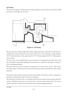
(4) Transfer The image developed by toner on the drum A is transferred onto the paper because of the electrical attraction between the toner itself and the transfer roller B. The transfer roller is negatively biased so that the positively charged toner is attracted onto the paper while it is pinched by the drum and the transfer roller. A Transfer bias High voltage board YC-T YC1-A5 YC1-A5 YC1-A7 YC1-A8 YC1-A8 B Bias board Engine board RTHVDR THVDR HVISEL PSEL1 PSEL2 YC11-14 YC12-2 YC11-12 YC11-9 YC11-7 Figure 4-1-9 Transfer The nominal transfer bias is set to approximately -1.8 kV (limit) with the -6 µA current. Since the ideal potential of the transfer bias depends on the thickness of paper, the bias is raised to approximately -2.5 kV/-6 µA for thicker paper. On the other hand, the bias current is reduced to -1.8 kV/-6 µA for thin paper. 4-11 FS-1050
-
 1
1 -
2
-
3
-
4
-
5
-
6
-
7
-
8
-
9
-
10
-
11
-
12
-
13
-
14
-
15
-
16
-
17
-
18
-
19
-
20
-
21
-
22
-
23
-
24
-
25
-
26
-
27
-
28
-
29
-
30
-
31
-
32
-
33
-
34
-
35
-
36
-
37
-
38
-
39
-
40
-
41
-
42
-
43
-
44
-
45
-
46
-
47
-
48
-
49
-
50
-
51
-
52
-
53
-
54
-
55
-
56
-
57
-
58
-
59
-
60
-
61
-
62
-
63
-
64
-
 65
65 -
 66
66 -
 67
67 -
 68
68 -
 69
69 -
 70
70 -
 71
71 -
 72
72 -
 73
73 -
 74
74 -
 75
75 -
76
-
77
-
78
-
79
-
80
-
81
-
82
-
83
-
84
-
85
-
86
-
87
-
88
-
89
-
90
-
91
-
92
-
93
-
94
-
95
-
96
-
97
-
98
-
99
-
100
-
101
-
102
-
103
-
104
-
105
-
106
-
107
-
108
-
109
-
110
-
111
-
112
-
113
-
114
-
115
-
116
-
117
-
118
-
119
-
120
-
121
-
122
-
123
-
124
-
125
-
126
-
127
-
128
-
129
-
130
-
131
-
132
-
133
-
134
-
135
-
136
-
137
-
138
-
139
-
140
-
141
-
142
-
143
-
144
-
145
-
146
-
147
-
148
-
149
-
150
-
151
-
152
-
153
-
154
-
155
-
156
-
157
-
158
-
159
-
160
-
161
-
162
-
163
-
164
-
165
-
166
-
167
-
168
-
169
-
170
-
171
-
172
-
173
-
174
-
175
-
176
-
177
 |
 |
