Pioneer VSX-1121-K Owner's Manual - Page 30
MULTI-ZONE setup, Making MULTI-ZONE connections, Connecting to the network through LAN interface
 |
View all Pioneer VSX-1121-K manuals
Add to My Manuals
Save this manual to your list of manuals |
Page 30 highlights
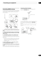
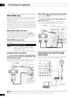
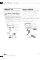
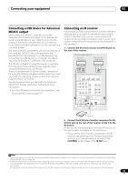
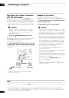
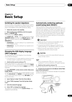
03 Connecting your equipment MULTI-ZONE setup This receiver can power up to two independent systems in separate rooms after you have made the proper MULTIZONE connections. Different sources can be playing in two zones at the same time or, depending on your needs, the same source can also be used. The main and sub zones have independent power (the main zone power can be off while the sub zone is on) and the sub zone can be controlled by the remote or front panel controls. Making MULTI-ZONE connections It is possible to make these connections if you have a separate TV and speakers for your primary (ZONE 2) sub zone. You will also need a separate amplifier if you are not using the MULTI-ZONE setup using speaker terminals (ZONE 2) below for your primary sub zone. MULTI-ZONE listening options The following table shows the signals that can be output to ZONE 2: Sub Zone ZONE 2 Input functions available DVD, TV/SAT, DVR/BDR, VIDEO, INTERNET RADIO, iPod/USB, CD, CD-R/TAPE, TUNER, ADAPTER PORT, SIRIUS (Outputs analog audio and composite video.) Basic MULTI-ZONE setup (ZONE 2) • Connect a separate amplifier to the AUDIO ZONE 2 OUT jacks and a TV monitor to the VIDEO ZONE 2 OUT jack, both on this receiver. You should have a pair of speakers attached to the sub zone amplifier as shown in the following illustration. Sub zone (ZONE 2) Main zone VIDEO IN AUDIO IN R L HDMI BD IN IN 1 ASSIGNABLE 14 COMPONENTVIDEO ASSIGNABLE Y PB PR IN 1 (DVD) IN 2 (DVR/BDR) ZONE2 OUT Y PB PR MONITOR OUT AM LOOP FM U RS-232C ANTENNA (OUTPUT 5 V 150 mA MAX) IN IN 1 OUT EXTENSION CONTROL MULTI-ZONE setup using speaker terminals (ZONE 2) You must select ZONE 2 in Speaker system setting on page 79 to use this setup. • Connect a TV monitor to the VIDEO ZONE 2 OUT jacks on this receiver. You should have a pair of speakers attached to the surround back speaker terminals as shown below. Sub zone (ZONE 2) Main zone VIDEO IN L R BD IN E IN 1 0/100) ADAPTER PORT (OUTPUT 5 V 100 mA MAX) NT VIDEO ASSIGNABLE PB PR OPTICAL ASSIGNABLE IN 2 IN 1 IN 2 IN 3 (CD) (TV/SAT) (DVR/BDR) (VIDEO) OUT ZONE2 ZONE3 OUTFRONT OUCTENTER SURROUND SURR BACK FH/FW (Single) PRE OUT L PB PR R AM LOOP SUBWOOFER FLM UNBALR SURROUND BACK L(Single) FRONT HEIGHT / FRONT W R C ANTENNA (OUTPUT 5 V 150 mA MAX) IN OUT 12 V T (OUTPU TOTAL 1 IN 1 IN XTENSION CONTROL IR Connecting to the network through LAN interface By connecting this receiver to the network via the LAN terminal, you can listen to Internet radio stations.1 OUT LAN (10/100) MONITOR OUT SIRIUS COAXIAL ASSIGNABLE IN IN 1 IN 2 (DVD) (CD) VIDEO OPTICAL ASSIGNABLE IN 1 IN 2 (TV/SAT) (DVR/BDR) DVR/BDR OUT IN CD IN AUDIO CD-R/TAPE OUT IN FRONT CENTER SURROUND SUBWOOFER FRONT L CENTER R SURROUND L R SURROUND BA Internet Modem LAN 3 2 1 WAN Router to LAN port LAN cable (sold separately) PC Note 1 To listen to Internet radio stations, you must sign a contract with an ISP (Internet Service Provider) beforehand. 30 En
-
 1
1 -
2
-
3
-
4
-
5
-
6
-
7
-
8
-
9
-
10
-
11
-
12
-
13
-
14
-
15
-
16
-
17
-
18
-
19
-
20
-
21
-
22
-
23
-
24
-
 25
25 -
 26
26 -
 27
27 -
 28
28 -
 29
29 -
 30
30 -
 31
31 -
 32
32 -
 33
33 -
 34
34 -
 35
35 -
36
-
37
-
38
-
39
-
40
-
41
-
42
-
43
-
44
-
45
-
46
-
47
-
48
-
49
-
50
-
51
-
52
-
53
-
54
-
55
-
56
-
57
-
58
-
59
-
60
-
61
-
62
-
63
-
64
-
65
-
66
-
67
-
68
-
69
-
70
-
71
-
72
-
73
-
74
-
75
-
76
-
77
-
78
-
79
-
80
-
81
-
82
-
83
-
84
-
85
-
86
-
87
-
88
-
89
-
90
-
91
-
92
-
93
-
94
-
95
-
96
-
97
-
98
-
99
-
100
-
101
-
102
-
103
-
104
-
105
-
106
-
107
-
108
 |
 |
