Pioneer VSX-1121-K Owner's Manual - Page 33
Connecting a USB device for Advanced MCACC output, Connecting an IR receiver, Connect
 |
View all Pioneer VSX-1121-K manuals
Add to My Manuals
Save this manual to your list of manuals |
Page 33 highlights
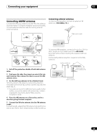
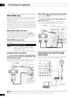
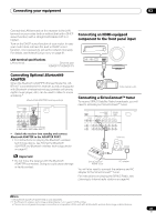
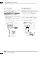
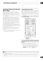
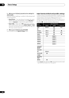
Connecting your equipment 03 Connecting a USB device for Advanced MCACC output When using Auto MCACC (page 69) or Acoustic Calibration EQ Professional (page 73) to calibrate the reverb characteristics of your listening room, the 3D graphs of the reverb characteristics in your listening room (before and after calibration) can be checked on a computer screen. The various MCACC parameters can also be checked on the computer. MCACC data and parameters are transferred from this receiver to a USB device and by connecting the USB device to a computer, the data is imported via the MCACC software in the computer. The MCACC software to output the results is available from the support area of the Pioneer website (http:// www.pioneerelectronics.com/PUSA/ Home+Entertainment+Custom+Install). Instructions for using the software are also available here. If you have any questions regarding, please contact the Customer Support Division of Pioneer. See the documentation provided with the Advanced MCACC PC Display Application Software for more information. • For the USB device connection and operations, see Output MCACC data on page 761. Connecting an IR receiver If you keep your stereo components in a closed cabinet or shelving unit, or you wish to use the sub zone remote control in another zone, you can use an optional IR receiver (such as a Niles or Xantech unit) to control your system instead of the remote sensor on the front panel of this receiver.2 1 Connect the IR receiver sensor to the IR IN jack on the rear of this receiver. Closet or shelving unit Pioneer component Non-Pioneer component CONTROL IR IN OUT IN HDMI BD IN IN 1 ASSIGNABLE 14 COMPONENTVIDEO ASSIGNABLE Y PB PR IN 1 (DVD) IN 2 (DVR/BDR) ZONE2 OUT Y PB PR MONITOR OUT IN IN 2 3 DVD TV/SAT IN IN AM LOOP RS-232C ANTENNA FM UNBAL 75 SPEAKERS A Class 2 Wiring (OUTPUT 5 V 150 mA MAX) IN IN OUT OUT 2 EXTENSION CONTROL IR IR receiver 2 Connect the IR IN jack of another component to the IR OUT jack on the rear of this receiver to link it to the IR receiver. Please see the manual supplied with your IR receiver for the type of cable necessary for the connection. • If you want to link a Pioneer component to the IR receiver, see Operating other Pioneer components with this unit's sensor below to connect to the CONTROL jacks instead of the IR OUT jack. Note 1 The various parameters and the reverb characteristics data used for display on the computer are not cleared when the power is turned off (see Output MCACC data on page 76). 2 • Remote operation may not be possible if direct light from a strong fluorescent lamp is shining on the IR receiver remote sensor window. • Note that other manufacturers may not use the IR terminology. Refer to the manual that came with your component to check for IR compatibility. • If using two remote controls (at the same time), the IR receiver's remote sensor takes priority over the remote sensor on the front panel. 33 En
-
 1
1 -
2
-
3
-
4
-
5
-
6
-
7
-
8
-
9
-
10
-
11
-
12
-
13
-
14
-
15
-
16
-
17
-
18
-
19
-
20
-
21
-
22
-
23
-
24
-
25
-
26
-
27
-
 28
28 -
 29
29 -
 30
30 -
 31
31 -
 32
32 -
 33
33 -
 34
34 -
 35
35 -
 36
36 -
 37
37 -
 38
38 -
39
-
40
-
41
-
42
-
43
-
44
-
45
-
46
-
47
-
48
-
49
-
50
-
51
-
52
-
53
-
54
-
55
-
56
-
57
-
58
-
59
-
60
-
61
-
62
-
63
-
64
-
65
-
66
-
67
-
68
-
69
-
70
-
71
-
72
-
73
-
74
-
75
-
76
-
77
-
78
-
79
-
80
-
81
-
82
-
83
-
84
-
85
-
86
-
87
-
88
-
89
-
90
-
91
-
92
-
93
-
94
-
95
-
96
-
97
-
98
-
99
-
100
-
101
-
102
-
103
-
104
-
105
-
106
-
107
-
108
 |
 |
