Brother International HE-800B Instruction Manual - English - Page 19
INSTALLATION, <Main P.C. board>, <Power supply P.C., board>, P.C. board
 |
View all Brother International HE-800B manuals
Add to My Manuals
Save this manual to your list of manuals |
Page 19 highlights
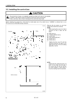
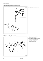
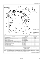
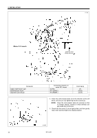
3. INSTALLATION Lock the cord clamp securely. 4746M Connector Cutter sensor 6-pin Feed sensor, thread breakage sensor 12-pin STOP switch 6-pin Safety switch 3-pin Machine head memory 6-pin Needle zigzag sensor, needle zigzag encoder 5-pin white Feed encoder 5-pin blue Work clamp sensor, work clamp encoder 5-pin black Needle zigzag motor 4-pin white Feed motor 4-pin blue Work clamp motor 4-pin black Tension release solenoid 4-pin Connection location on main P.C. board P7 (SENSOR2) P8 (SENSOR1) P9 (HEAD) P14 (HEAD-SW) P16 (HEAD-MEM) P17 (X-ENC) P18 (Y-ENC) P19 (P-ENC) P21 (XPM) P22 (YPM) P23 (PPM) P3 (SOL2) Cord clamp (4) (5) (4) (5) (4) (5) (5) (5) (5) (5) (5) (6) (6) (6) (6) Connector Cutter solenoid 4-pin Connection location on cutter P.C. board P2 (SOL) Cord clamp - NOTE: Route the needle zigzag, feed and work clamp motor harnesses and the tension release solenoid harness so that they do not touch the cutter P.C. board and the power supply P.C. board. (Continued on next page) HE-800B 10
-
 1
1 -
2
-
3
-
4
-
5
-
6
-
7
-
8
-
9
-
10
-
11
-
12
-
13
-
 14
14 -
 15
15 -
 16
16 -
 17
17 -
 18
18 -
 19
19 -
 20
20 -
 21
21 -
 22
22 -
 23
23 -
 24
24 -
25
-
26
-
27
-
28
-
29
-
30
-
31
-
32
-
33
-
34
-
35
-
36
-
37
-
38
-
39
-
40
-
41
-
42
-
43
-
44
-
45
-
46
-
47
-
48
-
49
-
50
-
51
-
52
-
53
-
54
-
55
-
56
-
57
-
58
-
59
-
60
-
61
-
62
-
63
-
64
-
65
-
66
-
67
-
68
-
69
-
70
-
71
-
72
-
73
-
74
-
75
-
76
-
77
-
78
-
79
-
80
-
81
-
82
-
83
-
84
-
85
-
86
-
87
-
88
-
89
-
90
-
91
-
92
-
93
-
94
-
95
-
96
-
97
-
98
-
99
-
100
-
101
-
102
-
103
-
104
-
105
-
106
 |
 |
