Cisco ISE Software Configuration Guide - Page 10
SUMMARY STEPS, DETAILED STEPS, Command or Action, Purpose - release notes
 |
UPC - 746320730097
View all Cisco ISE manuals
Add to My Manuals
Save this manual to your list of manuals |
Page 10 highlights
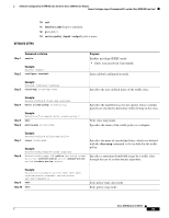
Software Configuration of ATM ISE Line Cards for Cisco 12000 Series Routers How to Configure Layer 3 Terminated VCs on the 4-Port ATM ISE Line Card Note For VBR connections in which the sustainable cell rate (SCR) is not equal to the PCR value, the CDVT is significantly lower. Decreased VC Throughput If you configure a VC on a 4-Port OC-12/STM-4 ATM ISE interface with a peak cell rate (PCR) or sustainable cell rate (SCR) greater than OC-6 (using the ubr, vbr-nrt, vbr-rt, or cbr commands), and attach a traffic policy with MDRR (configured using the bandwidth command) to the interface for specified traffic classes, when traffic on the interface from the specified classes is equal to or greater than the configured PCR or SCR values, frequent queueing and dequeueing changes occur between the MDRR queues and may cause a decreased VC throughput. Decreased throughput is more likely to occur when the traffic consist of small packets and when a high amount of traffic is sent toward the high-priority queue. Such traffic will increase significantly the frequency of switches between queues, which may cause the nonpriority queues to lose their bandwidth. Therefore, when configuring a VC to more than OC-6, it is recommended to limit the high priority traffic using the police command. SUMMARY STEPS Use either Step 5, Step 6, Step 7 or Step 8 depending on the desired shaping. 1. enable 2. configure terminal 3. interface atmslot/port.subinterface 4. pvc vpi/vci 5. cbr pcr 6. vbr-rt pcr scr 7. vbr-nrt pcr scr 8. ubr pcr DETAILED STEPS Command or Action Step 1 enable Step 2 Example: Router> enable configure terminal Step 3 Example: Router# configure terminal interface atmslot/port.subinterface Example: Router(config)# interface atm1/0.2 Purpose Enables privileged EXEC mode. • Enter your password if prompted. Enters global configuration mode. Specifies an ATM interface or subinterface to configure. Configure subinterfaces so that you can take advantage of access list definitions for the IP traffic. Cisco IOS Release 12.0(27)S 10
-
 1
1 -
2
-
3
-
4
-
 5
5 -
 6
6 -
 7
7 -
 8
8 -
 9
9 -
 10
10 -
 11
11 -
 12
12 -
 13
13 -
 14
14 -
 15
15 -
16
-
17
-
18
-
19
-
20
-
21
-
22
-
23
-
24
-
25
-
26
-
27
-
28
-
29
-
30
-
31
-
32
-
33
-
34
-
35
-
36
-
37
-
38
-
39
-
40
-
41
-
42
-
43
-
44
-
45
-
46
-
47
-
48
-
49
-
50
-
51
-
52
-
53
-
54
-
55
-
56
-
57
-
58
-
59
-
60
-
61
-
62
-
63
-
64
-
65
-
66
-
67
-
68
-
69
-
70
-
71
-
72
-
73
-
74
-
75
-
76
-
77
-
78
-
79
-
80
-
81
-
82
-
83
-
84
-
85
-
86
-
87
-
88
-
89
-
90
-
91
-
92
-
93
-
94
-
95
-
96
-
97
-
98
-
99
-
100
-
101
-
102
 |
 |
