Cisco ISE Software Configuration Guide - Page 5
How to Perform a Basic Configuration of the 4-Port ATM ISE Line Card, Configuring an ATM Interface - documentation
 |
UPC - 746320730097
View all Cisco ISE manuals
Add to My Manuals
Save this manual to your list of manuals |
Page 5 highlights
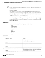
Software Configuration of ATM ISE Line Cards for Cisco 12000 Series Routers How to Perform a Basic Configuration of the 4-Port ATM ISE Line Card • Any Transport over Multiprotocol Label Switching (MPLS) [AToM]. • ATM OAM Emulation • Cell-based policing • Experimental bit marking • Cell packing for port, VC, and VP modes • Cell relay for port, VC, and VP modes How to Perform a Basic Configuration of the 4-Port ATM ISE Line Card The 4-port ATM ISE line cards provide the ability to configure Layer 2 AToM VCs as well as Layer 3 terminated VCs. On any individual ATM interface, you can configure both AToM VCs and terminated VCs as required. The configurations of these are discussed in subsequent sections in this document. This section provides basic ATM interface configuration information and discusses those features that are applicable to both AToM VCs and terminated VCs. Configuring ATM interfaces and virtual circuits is described in the following sections: • Configuring an ATM Interface, page 5 • Configuring UNI and NNI Cell Support, page 7 • Troubleshooting Tips, page 7 Configuring an ATM Interface Use the show running-config command to display current port configuration information. On power up, the interface on a new 4-Port ATM ISE line card is shut down. To enable the interface, you must enter a no shutdown command in configuration mode. Default Interface Configuration When the 4-Port ATM ISE line card is enabled (taken out of shutdown) with no additional configuration commands applied, the default interface configuration file parameters, described in Table 3, are used. Table 3 4-Port ATM ISE Line Card Default Configuration Values Parameter Maximum transmission unit (MTU) Maximum numbers of virtual circuits Loopback Internal clock SONET framing Configuration File Entry [no] mtu bytes [no] atm maxvc numvc [no] loopback [diagnostic | line] [no] atm clock internal [no] atm sonet stm-4 Default Value 4470 bytes 2047 no loopback no atm clock internal no atm sonet stm-4 2. Subject to overall system limitation and configuration. Cisco IOS Release 12.0(27)S 5
-
 1
1 -
 2
2 -
 3
3 -
 4
4 -
 5
5 -
 6
6 -
 7
7 -
 8
8 -
 9
9 -
 10
10 -
 11
11 -
12
-
13
-
14
-
15
-
16
-
17
-
18
-
19
-
20
-
21
-
22
-
23
-
24
-
25
-
26
-
27
-
28
-
29
-
30
-
31
-
32
-
33
-
34
-
35
-
36
-
37
-
38
-
39
-
40
-
41
-
42
-
43
-
44
-
45
-
46
-
47
-
48
-
49
-
50
-
51
-
52
-
53
-
54
-
55
-
56
-
57
-
58
-
59
-
60
-
61
-
62
-
63
-
64
-
65
-
66
-
67
-
68
-
69
-
70
-
71
-
72
-
73
-
74
-
75
-
76
-
77
-
78
-
79
-
80
-
81
-
82
-
83
-
84
-
85
-
86
-
87
-
88
-
89
-
90
-
91
-
92
-
93
-
94
-
95
-
96
-
97
-
98
-
99
-
100
-
101
-
102
 |
 |
