Cisco ISE Software Configuration Guide - Page 9
Troubleshooting Tips, Configuring ATM Shaping on Terminated VCs, Restrictions - 1 3 release
 |
UPC - 746320730097
View all Cisco ISE manuals
Add to My Manuals
Save this manual to your list of manuals |
Page 9 highlights
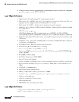
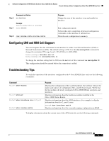
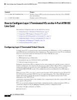
Software Configuration of ATM ISE Line Cards for Cisco 12000 Series Routers How to Configure Layer 3 Terminated VCs on the 4-Port ATM ISE Line Card The syntax of the atm pvp command is: atm pvp vpi vpi is the ATM network VPI to use for this virtual circuit, in the range of 0 to 255 for UNI or 0 to 4095 for NNI; vci is the ATM network VCI to use for this virtual circuit, in the range of 0 to 655,535. Troubleshooting Tips To display information about the connected virtual circuits, use the following commands: Command Router# show atm pvc Router# show atm vc Purpose Displays current ATM PVC information. Displays current ATM VC information. Configuring ATM Shaping on Terminated VCs The 4-Port ATM ISE line cards support IP traffic shaping on terminated VCs. The following ATM shaping options are available: • Constant bit rate (CBR)-Supports real-time applications that request a static amount of bandwidth that is continuously available for the duration of the connection. (See Step 5.) • Real-time variable bit rate (VBR-rt)-Supports real-time applications that have bursty transmission characteristics. (See Step 6.) • Non-real-time variable bit rate (VBR-nrt)-Supports non-real-time applications with bursty transmission characteristics that tolerate high cell delay, but require low cell loss. (See Step 7.) • Unspecified bit rate (UBR)-Supports non-real-time applications that tolerate both high cell delay and cell loss on the network. There are no network service-level guarantees for the UBR service category, and therefore it is a best-effort service. (See Step 8.) To configure ATM shaping, perform the shaping commands in PVC mode. You should use only one of the shaping commands in Step 5 through Step 8, depending on the type of shaping to be configured. Restrictions CDVT When traffic shaping is configured on a VC, the cell delay variation (CDV) is set for the VC. This value will change according to the shaping class defined. The cell delay variation tolerance (CDVT) values are shown in Table 4. Table 4 CDVT per Traffic Class for Traffic Shaping Traffic Class CBR UBR VBR-RT VBR-NRT OC-12c/STM-4c Line Card 70 μsec 185 μsec 70 μsec 185 μsec OC-3c/STM-1 Line Card 70 μsec 305 μsec 70 μsec 305 μsec Cisco IOS Release 12.0(27)S 9
-
 1
1 -
2
-
3
-
 4
4 -
 5
5 -
 6
6 -
 7
7 -
 8
8 -
 9
9 -
 10
10 -
 11
11 -
 12
12 -
 13
13 -
 14
14 -
15
-
16
-
17
-
18
-
19
-
20
-
21
-
22
-
23
-
24
-
25
-
26
-
27
-
28
-
29
-
30
-
31
-
32
-
33
-
34
-
35
-
36
-
37
-
38
-
39
-
40
-
41
-
42
-
43
-
44
-
45
-
46
-
47
-
48
-
49
-
50
-
51
-
52
-
53
-
54
-
55
-
56
-
57
-
58
-
59
-
60
-
61
-
62
-
63
-
64
-
65
-
66
-
67
-
68
-
69
-
70
-
71
-
72
-
73
-
74
-
75
-
76
-
77
-
78
-
79
-
80
-
81
-
82
-
83
-
84
-
85
-
86
-
87
-
88
-
89
-
90
-
91
-
92
-
93
-
94
-
95
-
96
-
97
-
98
-
99
-
100
-
101
-
102
 |
 |
