Cisco ISE Software Configuration Guide - Page 13
Command or Action, Purpose, OAM Management, OAM F5 Continuity Check, Example - 1 2 release notes
 |
UPC - 746320730097
View all Cisco ISE manuals
Add to My Manuals
Save this manual to your list of manuals |
Page 13 highlights
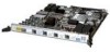
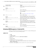
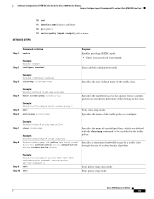
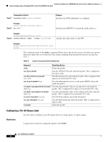
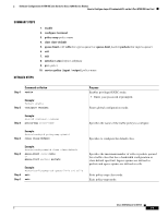
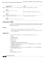
Software Configuration of ATM ISE Line Cards for Cisco 12000 Series Routers How to Configure Layer 3 Terminated VCs on the 4-Port ATM ISE Line Card Step 7 Command or Action oam-pvc manage cc {end | segment} [direction {both | sink | source}] [keep-vc-up [end aisrdi failure | seg aisrdi failure]] Purpose Configures ATM OAM F5 continuity check (CC) management to detect connectivity failures at the ATM layer. Step 8 Example: Router(config-if-atm-vc)# oam-pvc manage cc segment direction source oam retry cc {end | segment} [activation-count [deactivation-count [retry-frequency]]] Configures the retry count and the frequency at which CC activation and deactivation requests are sent to the device at the other end of the PVC or the segment. Example: Router(config-if-atm-vc)# oam retry cc segment 10 10 30 OAM Management By default, end-to-end F5 OAM loopback cell generation is turned off for each PVC. A PVC is determined as down when any of the following is true on that PVC: • The router does not receive a loopback reply after a configured number of retries of sending end-to-end F5 OAM loopback cells. • The router receives a Virtual Circuit-Alarm Indication Signal (VC-AIS) cell. The router receives a Virtual Circuit-Remote Detect Indicator (VC-RDI) cell. A PVC is determined as up when all the following are true on that PVC: • The router receives a configured number of successive end-to-end F5 OAM loopback cell replies. • The router does not receive VC-AIS cell for 3 seconds. • The router does not receive VC-RDI cell for 3 seconds. Note the following regarding OAM management: • When OAM management is not enabled, loopback (LB) cells received by the PVC are looped back to the sender, and for any received F4/F5-AIS, F4/F5-RDI cells are transmitted via this PVC, but the PVC state is not changed. The 4-Port ATM ISE line card supports OAM management enabled mode for the entire range of VCs supported, while using the default frequency of 10 seconds on all VCs. The minimum OAM LB cell frequency of 1 second is currently permitted over no more then 50 PVCs (chassis performance limitation), and the default interval of 10 seconds is used for the rest of the PVCs. OAM F5 Continuity Check The 4-Port ATM ISE line card also provides OAM support for the use of F5 segment and end-to-end continuity check (CC) cells to detect connectivity failures at the ATM layer. It also generates various Simple Network Management Protocol (SNMP) notifications when CC cells indicate virtual circuit (VC) connectivity failure ATM OAM F5 CC cells provide an in-service tool optimized to detect connectivity problems at the VC level of the ATM layer. CC cells are sent between a router designated as the source location and a router designated as the sink location. The local router can be configured as the source, the sink, or both. Cisco IOS Release 12.0(27)S 13
-
 1
1 -
2
-
3
-
4
-
5
-
6
-
7
-
 8
8 -
 9
9 -
 10
10 -
 11
11 -
 12
12 -
 13
13 -
 14
14 -
 15
15 -
 16
16 -
 17
17 -
 18
18 -
19
-
20
-
21
-
22
-
23
-
24
-
25
-
26
-
27
-
28
-
29
-
30
-
31
-
32
-
33
-
34
-
35
-
36
-
37
-
38
-
39
-
40
-
41
-
42
-
43
-
44
-
45
-
46
-
47
-
48
-
49
-
50
-
51
-
52
-
53
-
54
-
55
-
56
-
57
-
58
-
59
-
60
-
61
-
62
-
63
-
64
-
65
-
66
-
67
-
68
-
69
-
70
-
71
-
72
-
73
-
74
-
75
-
76
-
77
-
78
-
79
-
80
-
81
-
82
-
83
-
84
-
85
-
86
-
87
-
88
-
89
-
90
-
91
-
92
-
93
-
94
-
95
-
96
-
97
-
98
-
99
-
100
-
101
-
102
 |
 |
