Cisco ISE Software Configuration Guide - Page 22
Step 3, bandwidth
 |
UPC - 746320730097
View all Cisco ISE manuals
Add to My Manuals
Save this manual to your list of manuals |
Page 22 highlights
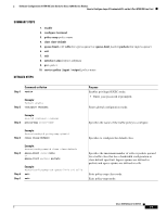
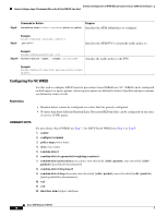
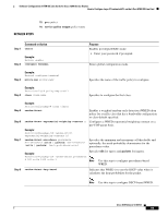
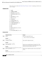
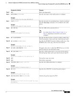
Software Configuration of ATM ISE Line Cards for Cisco 12000 Series Routers How to Configure Layer 3 Terminated VCs on the 4-Port ATM ISE Line Card Step 3 Command or Action policy-map policy-name Purpose Specifies the name of the traffic policy to configure. Step 4 Example: Router(config)# policy-map WRED-MDRR-POLICY-1 class class-name Specifies to configure the first class. Step 5 Step 6 Example: Router(config-pmap)# class class1 priority class class-name Specifies the class as the priority class. Specifies to configure the second class. Step 7 Example: Router(config-pmap)# class class2 bandwidth remaining percent percent Example: Router(config-pmap-c)# bandwidth remaining percent 50 Step 8 class class-default Step 9 exit Step 10 exit Step 11 interface atmslot/port.subifnum Specifies a minimum bandwidth guarantee to a traffic class. Here the minimum bandwidth guarantee is based on the remaining bandwidth available. If there is no available bandwidth, the class will receive no bandwidth, regardless of the percent specified. Explicitly specifies to configure the default class. Exits policy-map class mode. Exits policy-map mode. Specifies the ATM subinterface to configure. Step 12 Example: Router(config)# interface atm1/0.1 pvc vpi/vci Specifies the ATM PVC to attach the policy map to. Step 13 Example: Router(config-subif)# pvc 1/1 service-policy output policy-name Attaches the policy map to the PVC. Example: Router(config-if-atm-vc)# service-policy output WRED-MDRR-POLICY-1 Note If the class-default is not explicitly configured, it is implicitly configured. All remaining bandwidth is allocated to class-default. Note VCs with a configured bandwidth (using the bandwidth command) are limited to a peak cell rate (PCR) of 299,520 Kbps on the 4-Port OC-12c/STM-4c ATM ISE line card. Cisco IOS Release 12.0(27)S 22
-
 1
1 -
2
-
3
-
4
-
5
-
6
-
7
-
8
-
9
-
10
-
11
-
12
-
13
-
14
-
15
-
16
-
 17
17 -
 18
18 -
 19
19 -
 20
20 -
 21
21 -
 22
22 -
 23
23 -
 24
24 -
 25
25 -
 26
26 -
 27
27 -
28
-
29
-
30
-
31
-
32
-
33
-
34
-
35
-
36
-
37
-
38
-
39
-
40
-
41
-
42
-
43
-
44
-
45
-
46
-
47
-
48
-
49
-
50
-
51
-
52
-
53
-
54
-
55
-
56
-
57
-
58
-
59
-
60
-
61
-
62
-
63
-
64
-
65
-
66
-
67
-
68
-
69
-
70
-
71
-
72
-
73
-
74
-
75
-
76
-
77
-
78
-
79
-
80
-
81
-
82
-
83
-
84
-
85
-
86
-
87
-
88
-
89
-
90
-
91
-
92
-
93
-
94
-
95
-
96
-
97
-
98
-
99
-
100
-
101
-
102
 |
 |